Ultrasound diagnostic imaging system and method for 3D qualitative display of 2D border tracings

a diagnostic imaging and ultrasonic technology, applied in the field of medical ultrasound imaging, can solve the problem that the three-dimensional rendering of the target volume of interest may still contain inaccuracy, and achieve the effect of more accurate volume measuremen

Inactive Publication Date: 2005-05-12
KONINKLIJKE PHILIPS ELECTRONICS NV
View PDF6 Cites 85 Cited by
  • Summary
  • Abstract
  • Description
  • Claims
  • Application Information

AI Technical Summary

Benefits of technology

[0006] The method of the Prater et al. patent uses manual input from the clinician to define a ROI by a manual tracing. Accordingly, the method is performed on a stored image loop due to the need for manual input. In addition, the method of disks (Simpson's rule) volume estimation assumes that each disk is uniformly circular, which may not be the case. It would be desirable to estimate cavity volumes that are more closely related to the true shape of the anatomy rather than having to rely on an assumption of geometric uniformity of the anatomy, thus producing more accurate volume measures.

Problems solved by technology

However, such three-dimensional renderings of the target volume of interest may still contain inaccuracies, for example, misalignment of horizontal and vertical axes.

Method used


Image

  • Ultrasound diagnostic imaging system and method for 3D qualitative display of 2D border tracings
  • Ultrasound diagnostic imaging system and method for 3D qualitative display of 2D border tracings
  • Ultrasound diagnostic imaging system and method for 3D qualitative display of 2D border tracings

Examples


Embodiment Construction

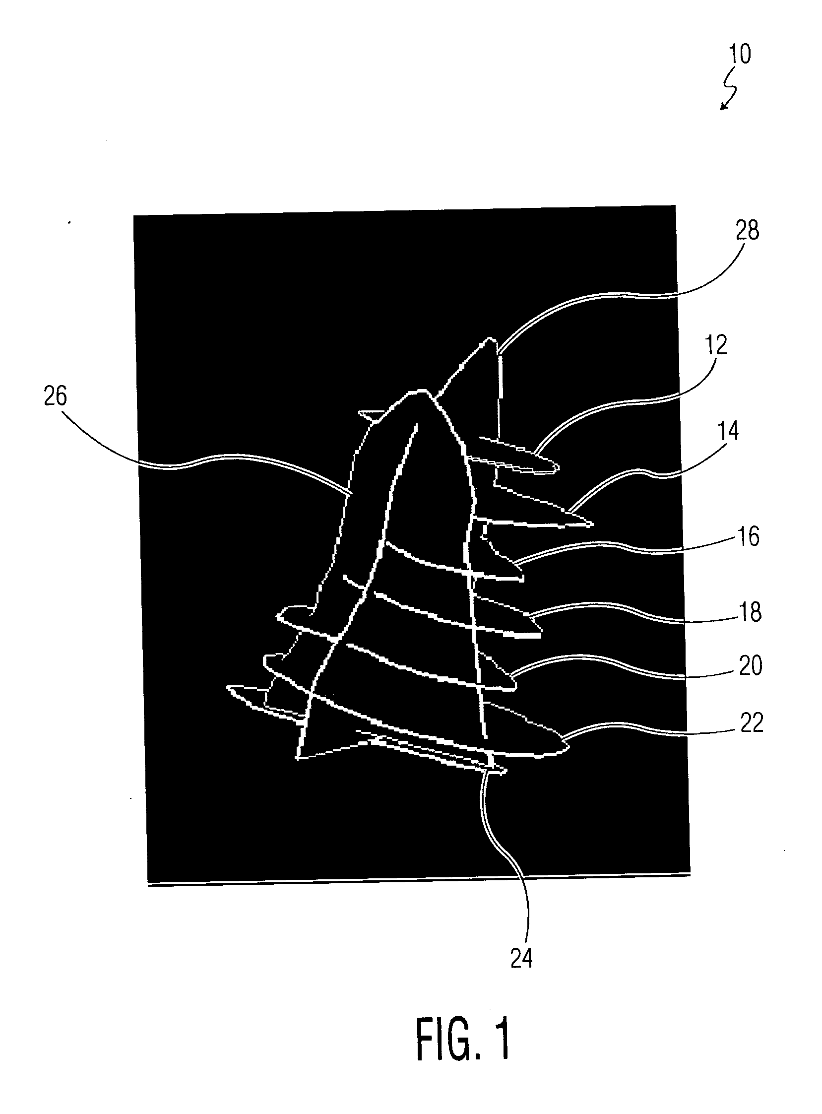
[0019] In connection with seeking improvements to ultrasound diagnostic imaging systems, the inventors of the embodiments of the present disclosure have discovered from 3D data sets used in constructing 3D volume views of an ultrasound image, in particular, for assessment of the left ventricle (LV) of the human heart, that short axis traces of the 3D volume views do not always coincide with long axis traces of the 3D volume views. The discrepancy between alignment of the short axis traces and the long axis traces is significant in that the traces should line up with each other.

[0020] According to an embodiment of the present disclosure, a method of implementing a 3D qualitative display includes the use of manual or automated 2D LV border tracings and the displaying of short axis traces and long axis traces of the 2D LV border tracings together. In other words, a display is provided that shows how a series of 2D borders drawn manually or automatically on multi-planar reformatted (MP...


PUM


Abstract

A method and system for generating a three-dimensional (3D) qualitative display (10,110,144) in an ultrasound system (30) include generating a first and a second two-dimensional (2D) slice (102,106,108) from a 3D data set of a 3D volume view of an ultrasound image. The first and second 2D slices (102,106,108) define a first and second plane of the 3D volume view along a first axis, wherein the second plane is orthogonal to the first plane. First and second border tracings (122,124) are generated around a portion of interest in the first and second 2D slices (102,106), respectively. A display (48) then displays (10,110) representations of the first and second border tracings within a single 3D view (10,128,130,146), wherein the 3D view provides an indication of alignment distortion of the first and second border tracings along the first axis. In one embodiment, at least one additional 2D slice defines an additional plane of the 3D volume view along a second axis, orthogonal to the first and second planes. Furthermore, at least one additional border tracing generated. The display (48) then further displays the at least one additional border tracing along the second axis within the single 3D view for providing an indication of alignment distortion of the first, second, and at least one additional border tracing along the first and second axes.

Description

CROSS REFERENCE TO RELATED CASES [0001] Applicants claim the benefit of Provisional Application Ser. No. 60 / 513,631, filed Oct. 23, 2003.BACKGROUND OF THE INVENTION [0002] The present disclosure generally relates to medical ultrasound imaging, and, more particularly, to an ultrasound diagnostic imaging system and method for 3D qualitative display of manual 2D LV border tracings. [0003] Echocardiographic ultrasonic imaging systems are used to assess the performance of the heart. Cardiac performance can be assessed qualitatively with these systems, such as by observing the blood flow through vessels and valves and the operation of heart valves. Quantitative measures of cardiac performance can also be obtained with such systems. For instance, the velocity of blood flow and the sizes of organs and cavities such as a heart chamber can be measured. These measures can produce quantified values of cardiac performance such as ejection fraction and cardiac output. [0004] One example of a meth...

Claims


Application Information

Patent Timeline
Patent Type & Authority Applications(United States)
IPC IPC(8): A61B5/107A61B8/06A61B8/08
CPCA61B5/1075A61B8/065A61B8/483A61B8/0883A61B8/08
Inventor ZHENG, CHUANSALGO, IVAN S.
Owner KONINKLIJKE PHILIPS ELECTRONICS NV
Why Eureka
Try Eureka