Shift control system of hybrid transmission

a technology of shifting control and hybrid transmission, which is applied in the direction of engine-driven generators, machines/engines, and jet propulsion mounting, etc., can solve the problems of unnaturally changing the driving torque and giving an unsuitable acceleration/deceleration feeling to the driver

Active Publication Date: 2005-05-12
NISSAN MOTOR CO LTD
View PDF13 Cites 117 Cited by
  • Summary
  • Abstract
  • Description
  • Claims
  • Application Information

AI Technical Summary

Benefits of technology

[0006] It is therefore an object of the present invention to provide a shift control system of a hybrid transmission which system solves the above-discussed problem.
[0007] An aspect of the present invention resides in a shift control system of a hybrid transmission for a vehicle. The hybrid transmission is constructed by connecting an internal combustion engine, an output shaft, and two motor/generators through a differential mechanism. The shift control system comprises a target value setting section setting a target driving torque, a target engine speed and a target engine torque according to a vehicle driving condition; an engine torque detecting section obtaining an actual engine torque; an ideal motor torque calculating section calculating ideal motor/generator torques of the motor/generators so as to achieve the target driving torque and the target engine revolution speed, from the target driving torque, the target engine speed and an actual en...

Problems solved by technology

However, this method causes a problem in case that a power transmission mechanism using this method is arranged to output a combination force of the force generated by the two motor/generators (electric devices) and a force generated by the internal combustion engine to a driveline.
That is, Japanese Published Patent Application No. 2002-058113 does not disclose a correction procedure of distributing the power of the motor/generators relative to the power of the engine although such a correction of a power distribution of the both ...

Method used


Image

  • Shift control system of hybrid transmission
  • Shift control system of hybrid transmission
  • Shift control system of hybrid transmission

Examples


Embodiment Construction

[0025] Hereinafter, there is discussed embodiments of a shift control system according to the present invention with reference to the drawings.

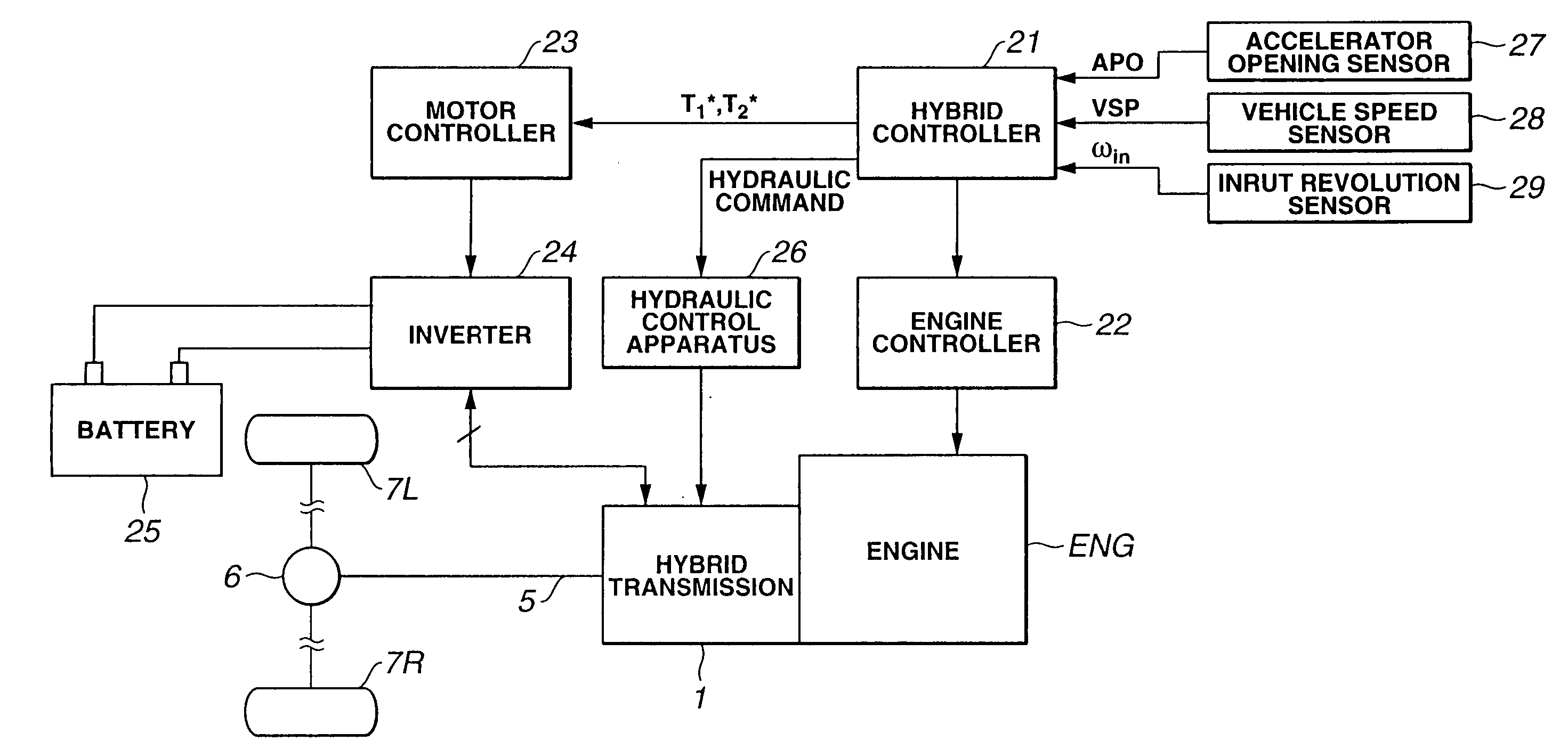
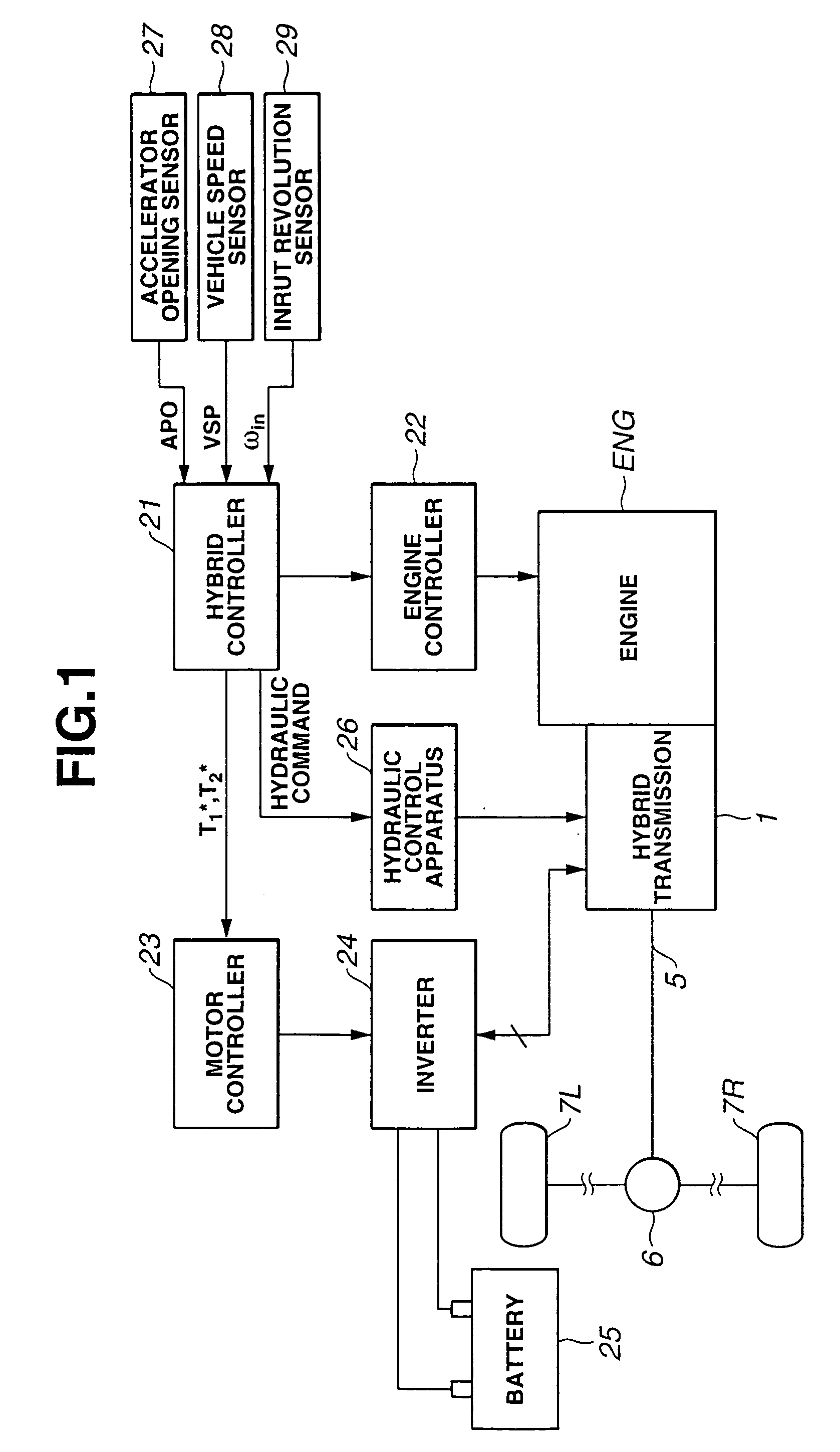
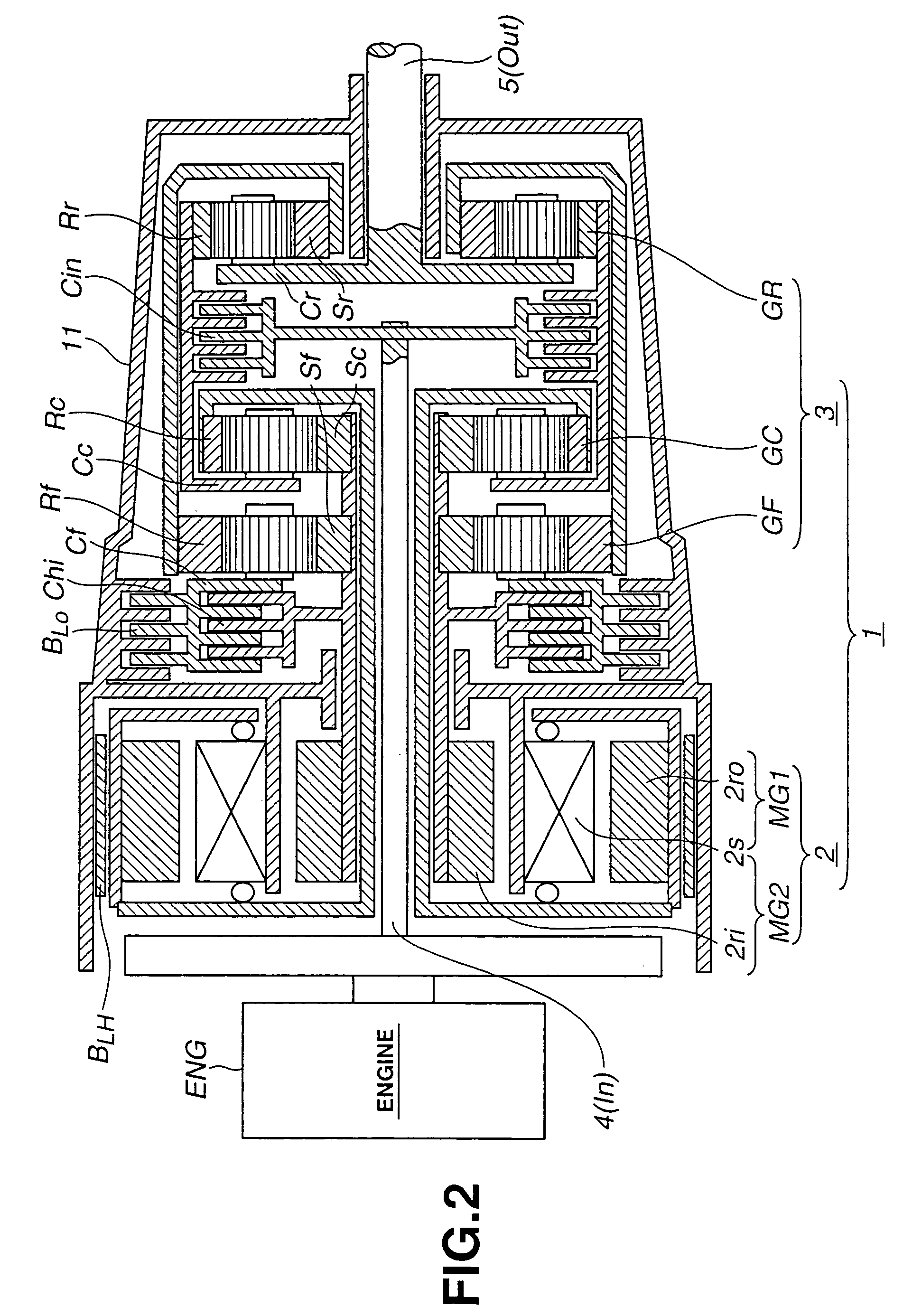
[0026]FIG. 1 shows a hybrid drive system which is for an automotive vehicle and comprises an internal combustion engine ENG and a hybrid transmission 1. A control system of hybrid transmission 1 comprises an embodiment of the shift control system according to the present invention. Hybrid transmission 1 is used as a transmission of a rear-drive vehicle and is constructed as shown in FIG. 2.

[0027] As shown in FIG. 2, hybrid transmission 1 comprises a transmission case 11 and three simple planetary gearsets GF, GC and GR disposed in transmission case 11. More specifically, front simple planetary gearset GF, center simple planetary gearset GC and rear simple planetary gearset GR are disposed in transmission case 11 so as to be coaxially arranged from a rear end apart from an engine ENG (a right hand side in FIG. 2) to a front end near engine E...


PUM


Abstract

A shift control system of a hybrid transmission for a vehicle is arranged to correct ideal motor/generator torques so as to achieve a target engine speed prior to a target driving torque when an actual engine speed becomes greater than an allowable upper-limit engine speed and to correct the ideal motor/generator torque so as to achieve the target driving torque prior to the target engine speed when the actual engine speed does not become greater than the allowable upper-limit engine speed.

Description

BACKGROUND OF THE INVENTION [0001] The present invention relates a hybrid drive system constructed by an internal combustion engine and a hybrid transmission including a differential mechanism and two motor / generator, and more particularly to a shift control system which appropriately executes a shift control of the hybrid transmission so as not to generate a strange acceleration / deceleration or an exceeding engine revolution due to an unnatural change of a driving torque or transmission ratio. [0002] It is known that a hybrid transmission is generally constructed by relationally connecting an internal combustion engine, an output shaft, two motor / generators and a differential mechanism to execute a shifting through the control of the two motor / generators. Such a hybrid transmission is arranged to drive the motor / generators using electric power of a battery. Accordingly, it is necessary to limit the electric power used for the motor / generators at a value smaller than a rated electri...

Claims


Application Information

Patent Timeline
IPC IPC(8): B60K1/02B60W20/00B60K6/445B60K6/54B60K17/04B60L9/18B60L50/16B60W10/04B60W10/06B60W10/08B60W10/10B60W10/101B60W10/26F02D29/00F02D29/02F16H3/72G06F7/00
CPCB60K1/02Y10T477/20B60K6/445B60K6/543B60L2240/423B60L2240/441B60W10/06B60W10/08B60W10/10B60W10/26B60W20/00B60W2510/0638B60W2710/083F16H3/728F16H2037/102F16H2037/104F16H2200/0039F16H2200/2005F16H2200/201F16H2200/2025Y02T10/6286Y02T10/642Y10S903/902Y10S903/903Y10S903/906Y02T10/6239Y10T477/23B60K6/365B60L7/14B60L15/2045B60L15/2054B60L2240/12B60L2240/14B60L2240/36B60L2240/421B60L2240/507B60L2240/547B60L2240/549B60L2250/26Y02T10/72B60L50/62B60L50/16B60L58/15Y02T10/62Y02T10/64Y02T10/70Y02T10/7072B60W20/11B60W2710/0666
Inventor JOE, SHINICHIROOSHIDARI, TOSHIKAZU
Owner NISSAN MOTOR CO LTD
Why Eureka
Try Eureka