Roll stability control system for an automotive vehicle using an external environmental sensing system

a technology of external environment and stability control, applied in anti-theft devices, instruments, tractors, etc., can solve the problems of inability to direct measurement, inability to provide enough fidelity for a rollover event, and inability to address the roll of the vehicle in the dynamic control system

Inactive Publication Date: 2005-05-12
FORD MOTOR CO +1
View PDF39 Cites 85 Cited by
  • Summary
  • Abstract
  • Description
  • Claims
  • Application Information

AI Technical Summary

Benefits of technology

[0012] One advantage of the invention is that the camera, radar, lidar, or sonar-based systems can be used alone or together with various sensors. The camera, radar, lidar, or sonar-based systems may provide a check to the sensor outputs.
[0013] Other objects and features of the present invention will become apparent when viewed in light of the detailed description of the preferred embodiment when taken in conjunction with the attached drawings and appended claims.

Problems solved by technology

Typically, the dynamic control systems do not address roll of the vehicle.
Although the vehicle attitude is well defined, direct measurement is usually impossible.
However driving on a three-dimensional road with moderate road bank angle, the global attitude may not be able to provide enough fidelity for a rollover event to be distinguished.
Vehicular rollover happens when one side of the vehicle is lifted from the road surface with a long duration of time without returning back.
However, during a potential rollover event, such a relative roll angle is not a good measure of the true relative roll angle between vehicle body and the road surface.
If the vehicle has large loading variations (especially roof loading), potential inaccuracy could cause false activations in roll stability controls.
Although this method is theoretically feasible, it has inevitable drawbacks.
The first drawback lies in the computation of the road bank angle, since there is no robust and accurate computation of road banks using the existing sensor set.
Secondly, the global roll angle computation as shown in U.S. Pat. No. 6,631,317 may be affected by the accuracy of the low frequency bank angle estimation.
Therefore, the aforementioned two methods of computing the body-to-road roll angle may not deliver accurate enough body-to-road roll angle for roll stability control purpose in certain situations.
These systems, however, do not prevent the vehicle from rolling over.

Method used


Image

  • Roll stability control system for an automotive vehicle using an external environmental sensing system
  • Roll stability control system for an automotive vehicle using an external environmental sensing system
  • Roll stability control system for an automotive vehicle using an external environmental sensing system

Examples


Embodiment Construction

[0021] In the following figures the same reference numerals will be used to identify the same components.

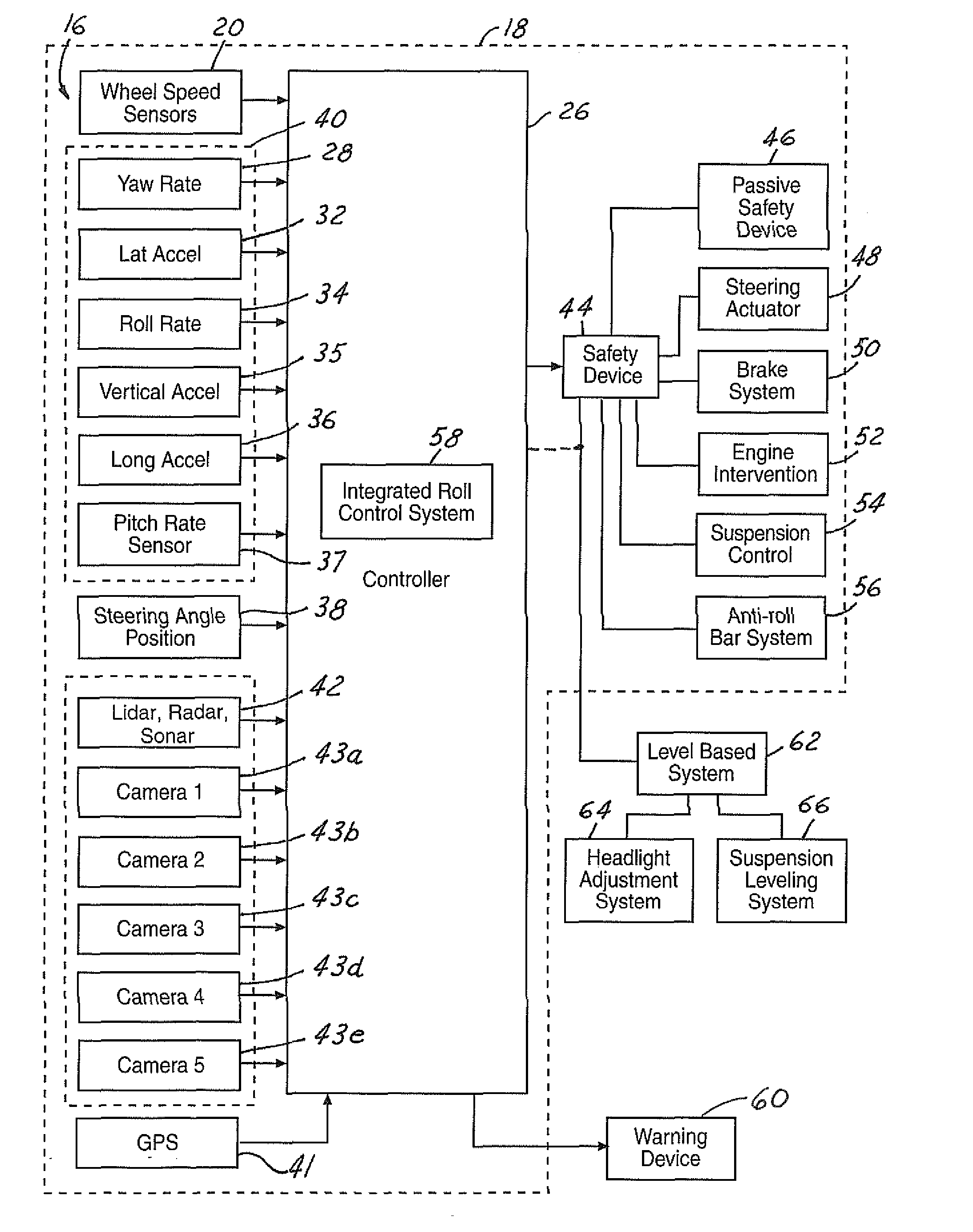
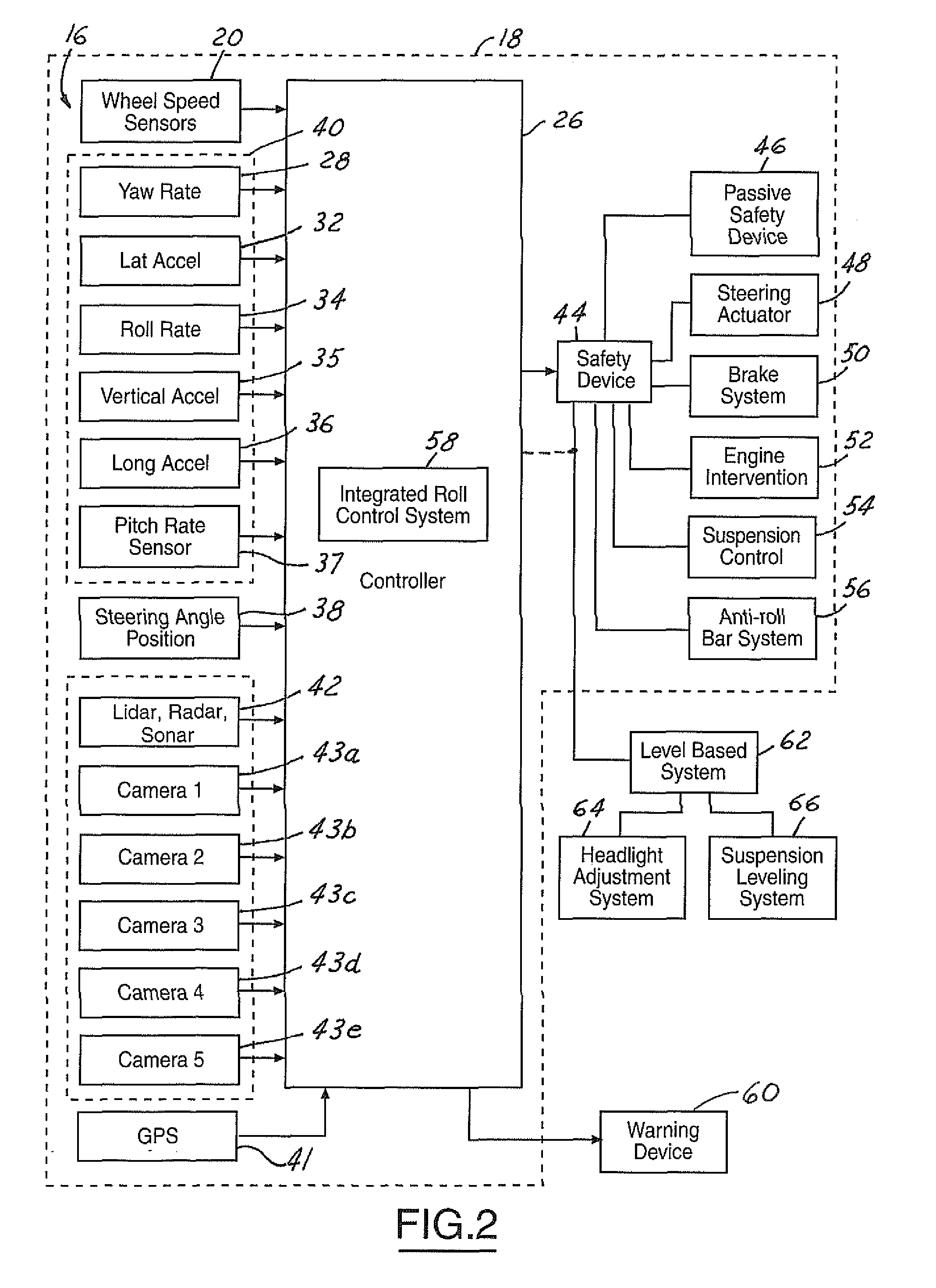
[0022] The present invention may be used in conjunction with a rollover control system for a vehicle. The system may be used with various dynamic control systems such as, but not limited to, anti-lock brakes, traction control and yaw control systems. The present invention will be discussed below in terms of preferred embodiments relating to an automotive vehicle moving in a three-dimensional road terrain. Further, the various image detection and sensors may be used alone or in various combinations depending on the conditions. For example, sensors may be used to check the image or radar signals or vice versa.

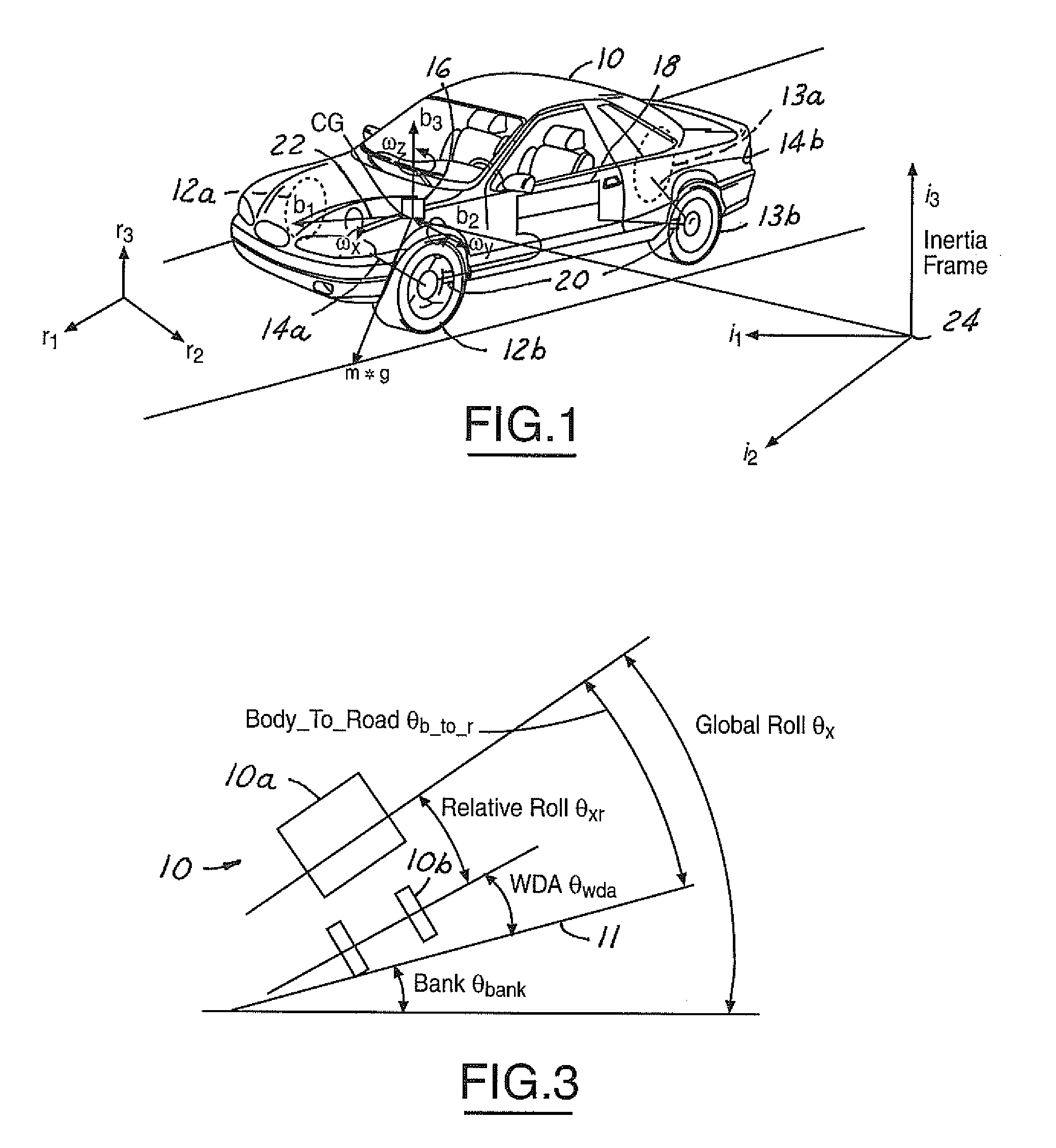
[0023] Referring to FIG. 1, an automotive vehicle 10 with a safety system of the present invention is illustrated with the various forces and moments thereon during a rollover condition. Vehicle 10 has front right and front left tires 12a and 12b and rear right tires 13a and...


PUM


Abstract

A roll stability control system (18) for an automotive vehicle (10) includes an external environment sensing system, such as a camera-based vision system, or a radar, lidar or sonar-based sensing system (43) that generates image, radar, lidar, and/or sonar-based signals. A controller (26) is coupled to the sensing system and generates dynamic vehicle characteristic signals in response to the image, radar, lidar, or sonar-based signals. The controller controls the rollover control system (18) in response to the dynamic vehicle control signal. The dynamic vehicle characteristics may include roll related angles, angular rates, and various vehicle velocities.

Description

BACKGROUND OF INVENTION [0001] The present invention relates generally to a dynamic behavior control apparatus for an automotive vehicle, and more specifically, to a method and apparatus for controlling the roll characteristics of the vehicle by determining roll characteristics using at least in part a camera, radar, lidar, or sonar-based system. [0002] Dynamic control systems for automotive vehicles have recently begun to be offered on various products. Dynamic control systems typically control the yaw of the vehicle by controlling the braking effort at the various wheels of the vehicle. Yaw control systems typically compare the desired direction of the vehicle based upon the steering wheel angle and the direction of travel. By regulating the amount of braking at each corner of the vehicle, the desired direction of travel may be maintained. Typically, the dynamic control systems do not address roll of the vehicle. For high profile vehicles in particular, it would be desirable to co...

Claims


Application Information

Patent Timeline
Patent Type & Authority Applications(United States)
IPC IPC(8): G06F19/00
CPCB60R21/0132B60W10/04B60W10/18B60W10/20B60W10/22B60W2550/20B60W2510/20B60W2520/105B60W2520/14B60W2520/16B60W2520/18B60W30/04B60W2554/00B60W2540/18
Inventor XU, LIWENBEYDOUN, SAMIR M.ENGELMAN, GERALD H.MILLS, AARON L.LU, JIANBOMATTSON, KEITH GLENN
Owner FORD MOTOR CO
Why Eureka
Try Eureka