Load balancing system

a load balancing and load technology, applied in the field of load balancing systems, can solve problems such as deteriorating system performance, and achieve the effects of preventing the overload of requests to the service servers, and preventing the reduction of service performan

Inactive Publication Date: 2005-05-12
HITACHI LTD
View PDF3 Cites 160 Cited by
  • Summary
  • Abstract
  • Description
  • Claims
  • Application Information

AI Technical Summary

Benefits of technology

[0008] In a load balancing system for distributing requests to a plurality of service servers in accordance with the present invention, information obtained by statistically processing an access log is used for load balancing control over the service servers to beforehand prevent the reduction of a service performance caused by the overload requests to the service servers.
[0009] In an aspect of a load balancing system in accordance with the present invention, the system includes a load balancer and an administration server, and the administration server statistically processes an access log. On the basis of the number of requests per unit time obtained from the statistical processing, the administration server predicts the number of service servers necessary for each time slot and informs the predicted number to the load balancer. The load balancer sets, according to the informed information about the time slot and the number of service servers, sets the distribution to a necessary number of service servers immediately before the specified time slot. As a result, the overload of requests to the service servers can be avoided and the reduction of the service performance can be beforehand prevented.
[0010] Further, when a special assignment day (which will be referred to as the access special day, hereinafter), on which an access pattern different from a usual pattern is already found or predicted, is specified, statistical processing different from the usual pattern is carried out on the special day and distribution setting unique to the special day is carried out, thus enabling suitable access control.
[0011] In accordance with the present invention, improved load balancing control can be realized and a high quality of service can be provided.

Problems solved by technology

The usual load balancing system disclosed in the Japanese Laid Open Patent Publication No. 2003-178041 is, however, designed to be based on removing the cause when an overload takes place and it tends to deteriorate the system performance.

Method used


Image

  • Load balancing system
  • Load balancing system
  • Load balancing system

Examples


Embodiment Construction

[0024] Explanation will be made in connection with an embodiment of the present invention, with reference to the accompanying drawings.

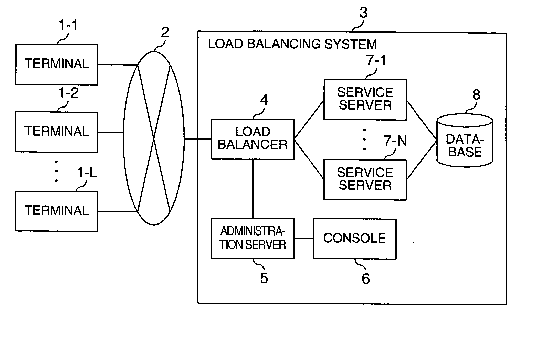
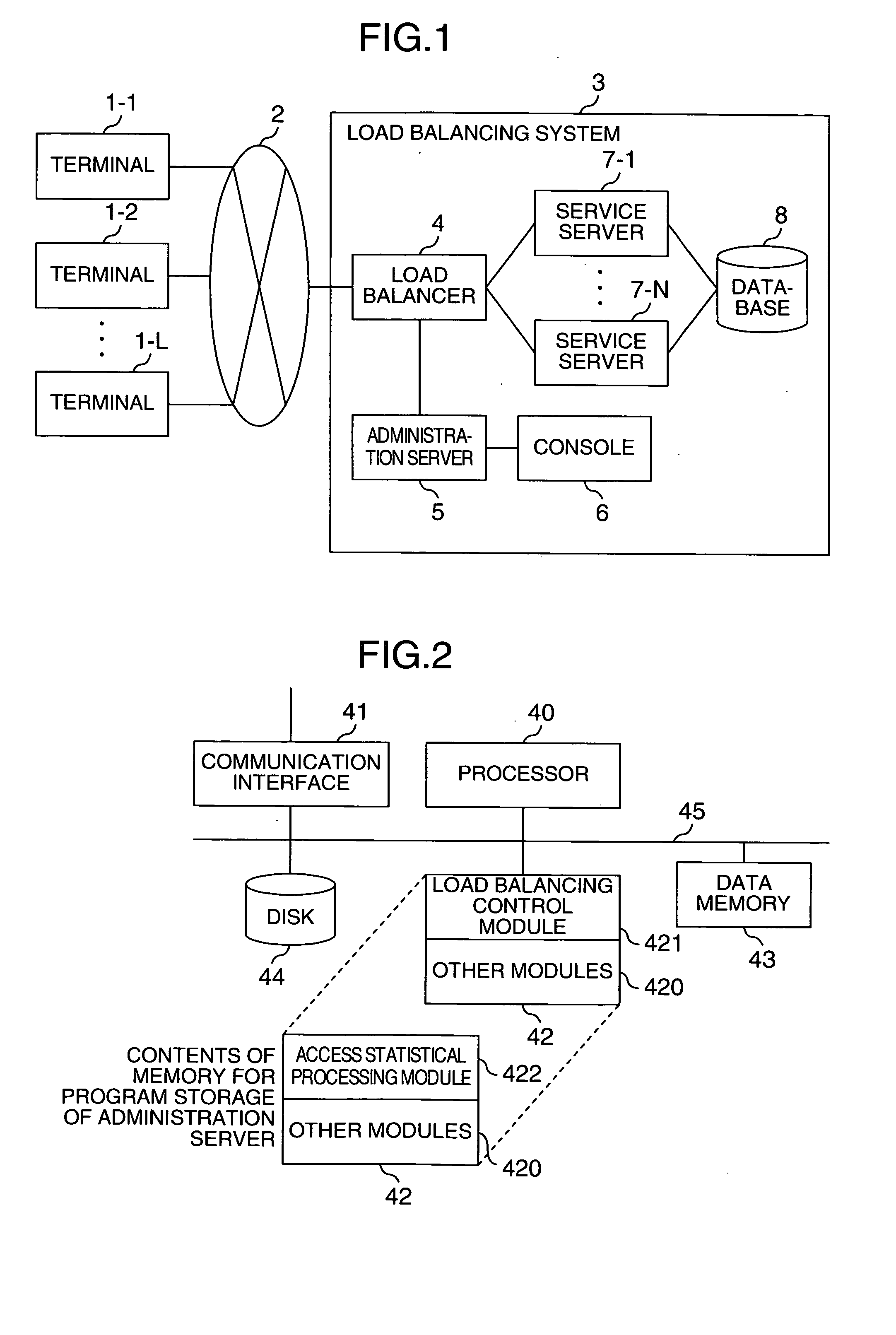
[0025]FIG. 1 shows a configuration of a communication network system including a load balancing system 3 according to the present embodiment.

[0026] The load balancing system 3 is connected to a plurality of client terminals (which will be referred to as the terminals, hereinafter) 1 (1-1 to 1-L) via a communication network 2 such as LAN or Internet.

[0027] The load balancing system 3 includes a load balancer 4 connected to the communication network 2, an administration server 5 having a communication function with the load balancer 4, a console 6 connected to the administration server, service servers 7 (7-1 to 7-N) connected to the load balancer 4, and a database 8 connected to the service servers 7. In this connection, the administration server 5 can communicate with the service servers 7 via the load balancer 4.

[0028] In the example of FIG. 1, ...


PUM


Abstract

A load balancing system having a plurality of service servers and a load balancer which prevents a service performance from being reduced by an overload of requests on the service servers. The system includes a load balancer and a administration server, the load balancer outputs an access log relating to an access to the service server, and the administration server performs statistical operation over the access log. The administration server prepares a service server run schedule on the basis of a result of the statistical operation and informs the load balancer of it. The load balancer controls distribution of a request to the service server according to the informed run schedule.

Description

BACKGROUND OF THE INVENTION [0001] The present invention relates to a load balancing system for distributing an access to a plurality of servers and more particular, to a method for running a load balancer. [0002] As the Internet spreads, conventional services including ticket sale so far done at a ticket window have been realized in the Internet. As communication techniques advances, in addition, there has been arranged such an environment that the same services can be accepted not only from homes or offices but also from portable phones. [0003] A service provider server (which will be referred to as the service server, hereinafter) for providing such services as mentioned above via the Internet is usually required to process requests from a multiplicity of client terminals, and thus such many requests cannot be processed by such a single service server. For this reason, there is known a system which includes a plurality of service servers connected to a load balancer, and wherein ...

Claims


Application Information

Patent Timeline
Patent Type & Authority Applications(United States)
IPC IPC(8): G06F9/50H04L29/06G06F13/00H04L29/08
CPCH04L29/06H04L2029/06054H04L67/1023H04L67/1002H04L67/1008H04L67/10015H04L67/1001H04L9/40
Inventor NAKAHARA, MASAHIKONAGAMI, AKIHISANODA, FUMIO
Owner HITACHI LTD
Why Eureka
Try Eureka