Tree shelter

Inactive Publication Date: 2005-05-19
JONES ADRIANNE JACQUELINE
View PDF10 Cites 22 Cited by
  • Summary
  • Abstract
  • Description
  • Claims
  • Application Information

AI Technical Summary

Benefits of technology

[0037] Preferably, the resin-covered mat is cut into a substantially rectangular panel. In a first embodiment, at least one projecting tab is formed along one edge of the panel which can be inserted into a slit cut close to an opposing edge of the panel to enable the rectangular

Problems solved by technology

It has been found, however, that such supports do not fully degrade within the time frame but disintegrate gradually between three and ten years into separate pieces so that the unsightly remains of the supports can still be present around the tree or shrub for some considerable time.
As much tree and shrub planting is carried out for landscaping purposes, having disintegrating supports still visible some years after planting is undesirable and in order to remedy the situation it is common practic

Method used


Image

  • Tree shelter
  • Tree shelter
  • Tree shelter

Examples


first embodiment

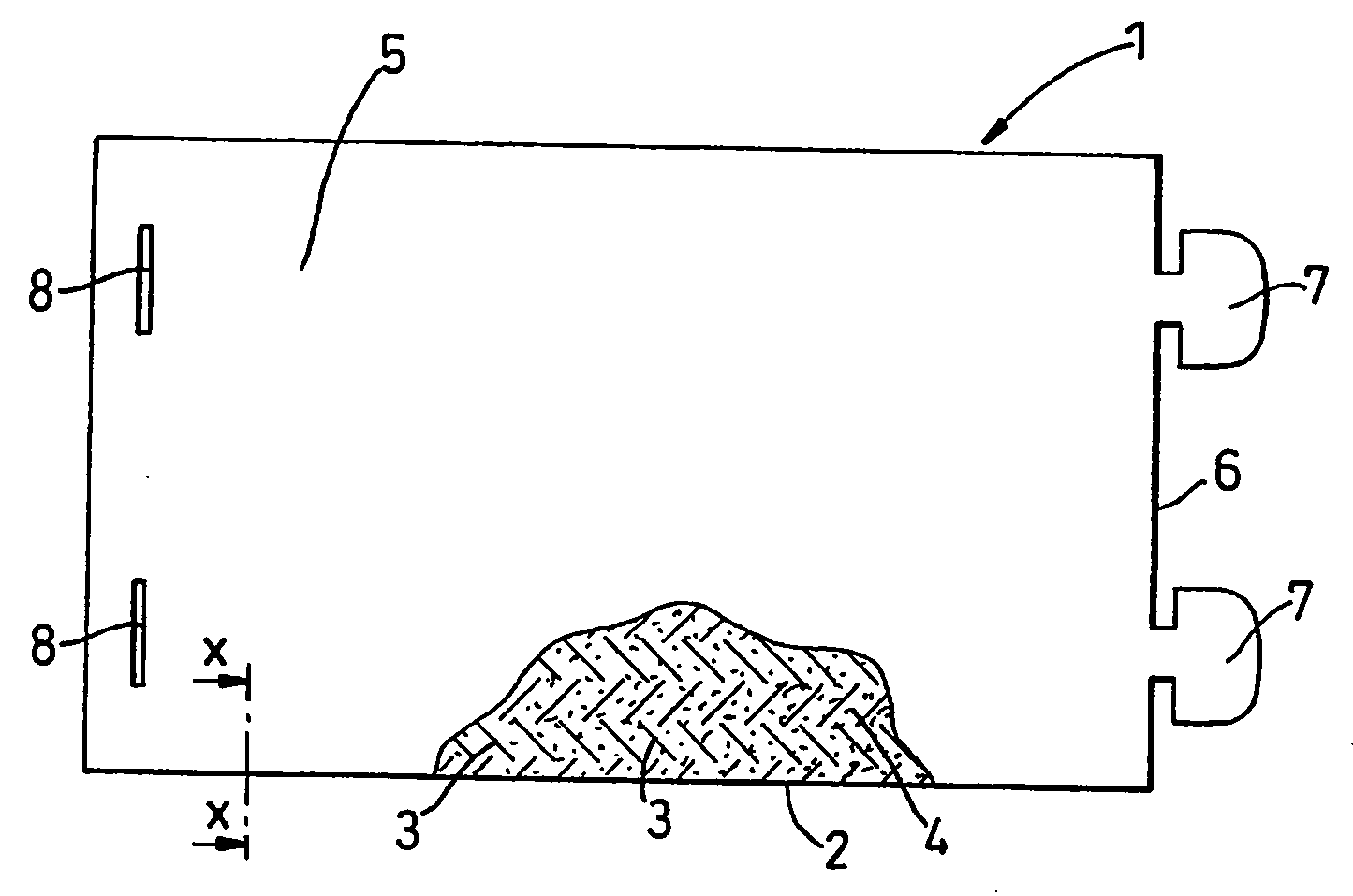
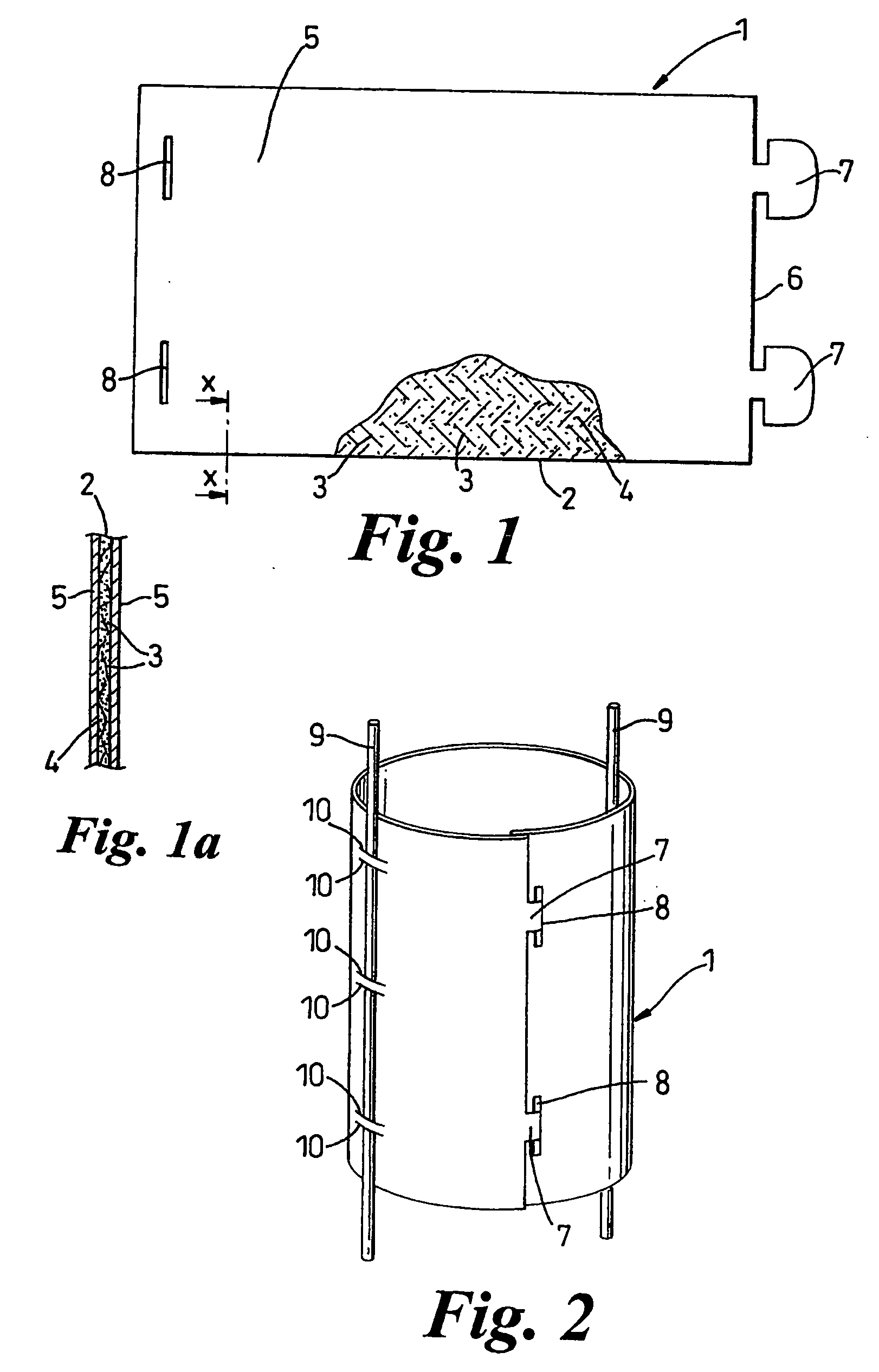
[0054] In a first embodiment as shown in FIGS. 1 and 2, along one of the shorter edges of the panel 6 are formed two spaced, projecting tabs 7 and along the opposing edge are cut two slits 8 that correspond to the positions of the tabs 7 so that when the panel 6 is rolled up, each tab 7 can be inserted into a corresponding slit 8 to retain the panel 4 in a rolled state, as shown in FIG. 2. The tabs 7 have been shaped for this purpose by being made spoon-shaped, as shown in FIG. 1, in known fashion so that once inserted into the slits 8 they cannot easily be pulled out of position.

[0055] Alternatively, the tabs 7 could be made arrow-shaped.

[0056] The rolled-up panel 6 shown in FIG. 2 has been provided with two stakes 9. These stakes 9 may be fastened to the panel 6 by weaving the stakes 9 through slits 10 cut appropriately in the panel 4 for this purpose. Both of the stakes 9 are used to anchor the shelter 1 to ground and one of them may also be secured to the plant being protected,...

second embodiment

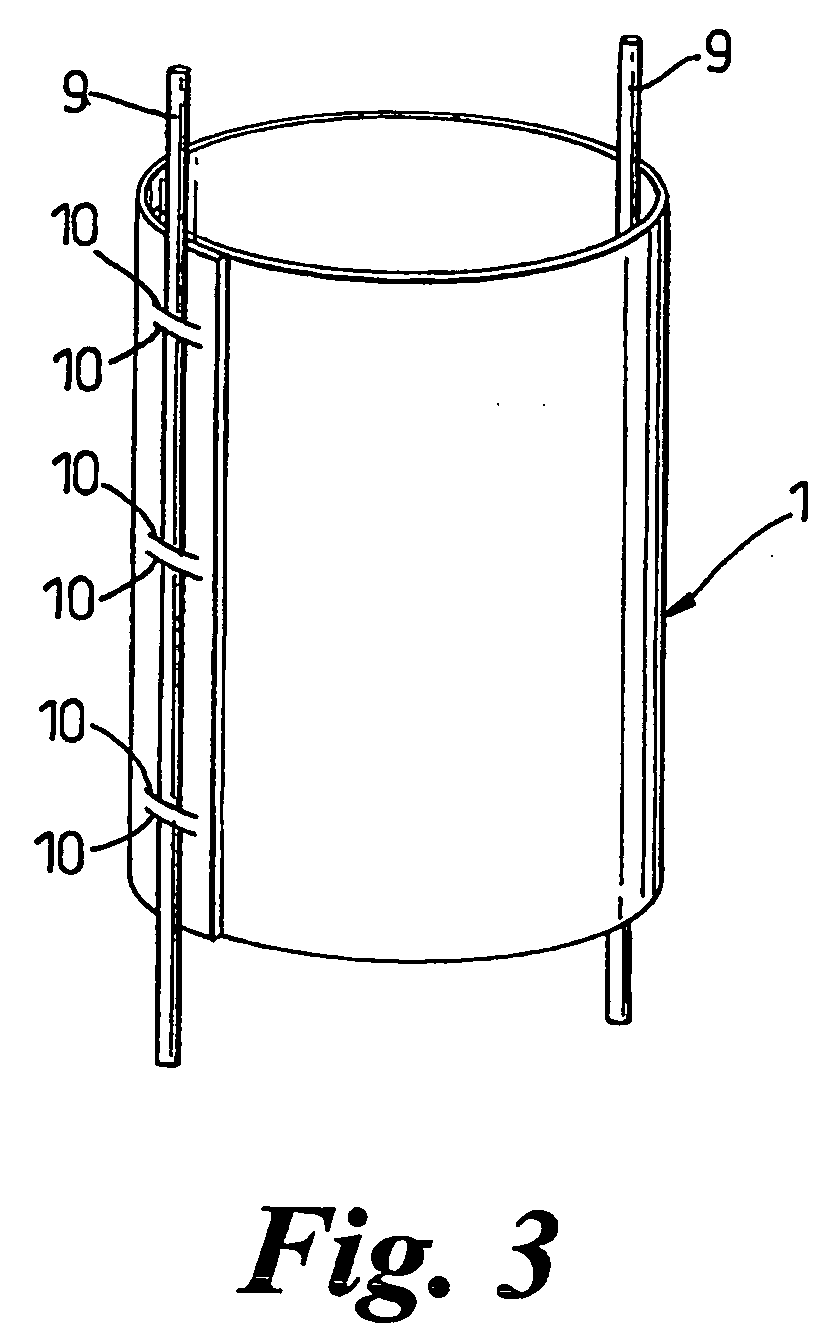
[0057] In a second embodiment, as shown in FIG. 3, the mat is cut into a rectangular panel that is provided with a plurality of slits similar to the slits 10 along two opposing edges. When the panel is rolled up, a stake 9 can be woven through the slits 10 in the overlapping portion of the panel to retain the shelter 1 in a rolled-up state before being pushed into the ground as an anchor. No additional fixing mechanism to retain the shelter in a rolled state is therefore required in this embodiment.

[0058] It will be appreciated that in use, the tree shelter 1 of the invention is stored and transported in panel form and only assembled into a rolled-state on site. This facilitates the storage and transportation of the shelter 1 as compared to conventional shelters which are usually manufactured in a tubular form.

[0059] In use, as shown schematically in FIG. 4, the shelter 1 is staked to the ground close to a tree or plant 11, such as a sapling, and then rolled up around the stem or t...


PUM


Abstract

A tree shelter includes a biodegradable fibrous mat coated with a degradable resin and adapted to be formed into a roll which can enclose at least the lower part of a plant. The mat is preferably non-woven and its structure is preferably impregnated with a second degradable resin which degrades at a different, preferably faster, rate to that of the first degradable resin under the same environmental conditions. Such a shelter has the advantage that once the first resin has substantially degraded over a predetermined time period to expose the mat to the weather, the second degradable resin commences a faster degradation to cause the mat to decompose rapidly into a loose fibrous state and ultimately form a beneficial mulch around the stem or trunk at the base of the plant.

Description

RELATED U.S. APPLICATIONS [0001] Not applicable. STATEMENT REGARDING FEDERALLY SPONSORED RESEARCH OR DEVELOPMENT [0002] Not applicable. REFERENCE TO MICROFICHE APPENDIX [0003] Not applicable. FIELD OF THE INVENTION [0004] The present invention relates to a tree shelter and, in particular, to a degradable tree shelter and preferably one which is fully biodegradable. BACKGROUND OF THE INVENTION [0005] The term “tree shelter” when used herein and in the claims should be understand as meaning a shelter suitable for use with any form of plant, either woody or herbaceous, and not as only suitable for use with trees. [0006] When young trees and shrubs are first planted, it is desirable to provide them with support and protection from damage caused by adverse weather conditions, such as high winds, ground erosion and animals. Typically, this is done by means of a tree shelter which encloses at least the lower part of the tree or shrub in a tubular support. [0007] Conventional tree shelters ...

Claims


Application Information

Patent Timeline
IPC IPC(8): A01G13/02A01G13/10
CPCA01G13/0243
Inventor JONES, ADRIANNE JACQUELINE
Owner JONES ADRIANNE JACQUELINE
Why Eureka
Try Eureka