Multi-point lock

Inactive Publication Date: 2005-05-19
ASSA ABLOY FINANCIAL SERVICES
View PDF11 Cites 48 Cited by
  • Summary
  • Abstract
  • Description
  • Claims
  • Application Information

AI Technical Summary

Benefits of technology

[0008] It is an object of the present invention to provide a multi-point lock,

Problems solved by technology

Some known locks suffer from being very complex in construction which results in multiple components.
This leads to not only increased manufacturing costs but also costs associated with assembly of the lock.
The complexity of many known locks can lead to complexity in operation of the lock by a user.
This can lead to a further disadvantage with some known locks where it is difficult to achieve suffi

Method used


Image

  • Multi-point lock
  • Multi-point lock
  • Multi-point lock

Examples


Embodiment Construction

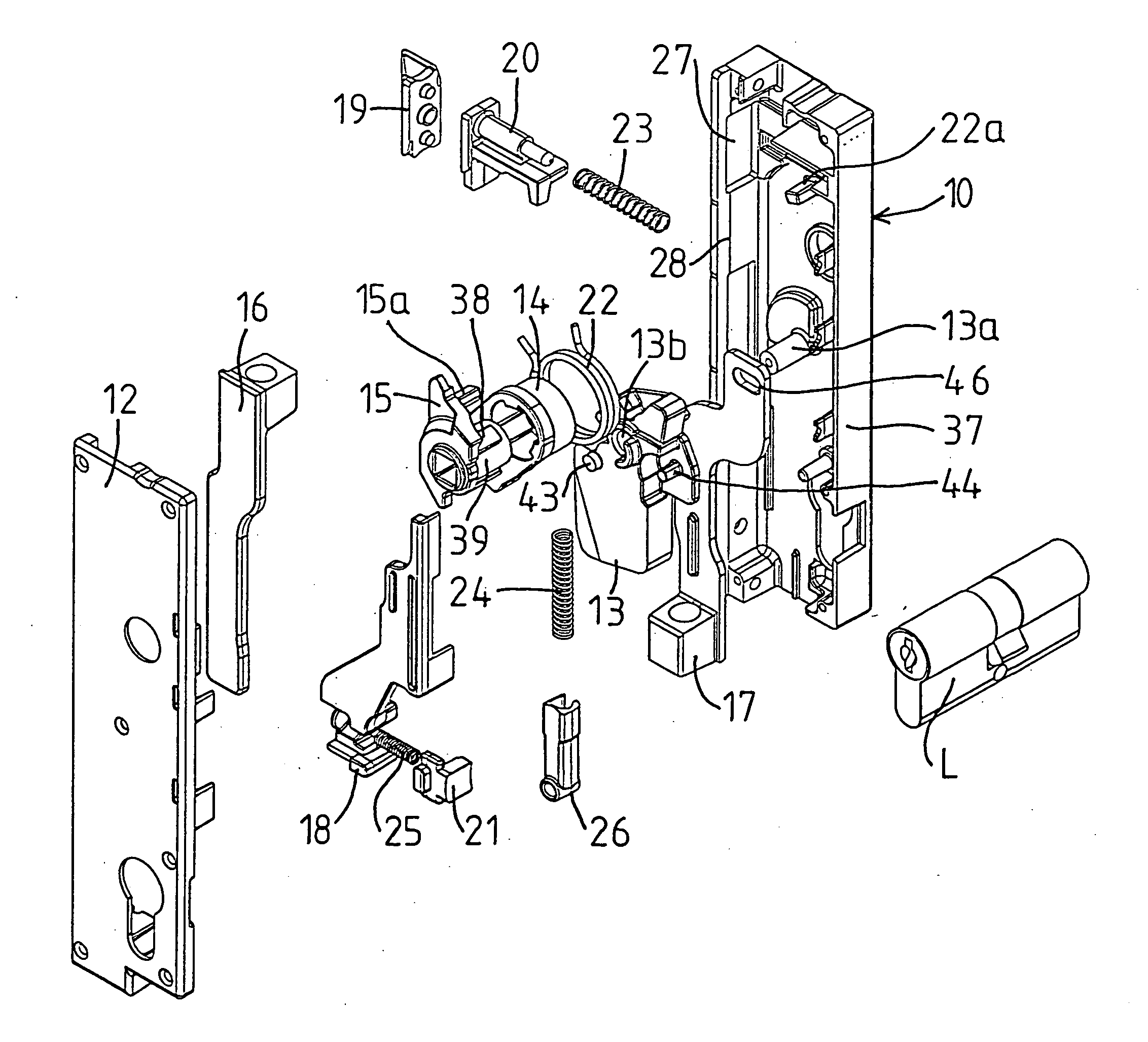
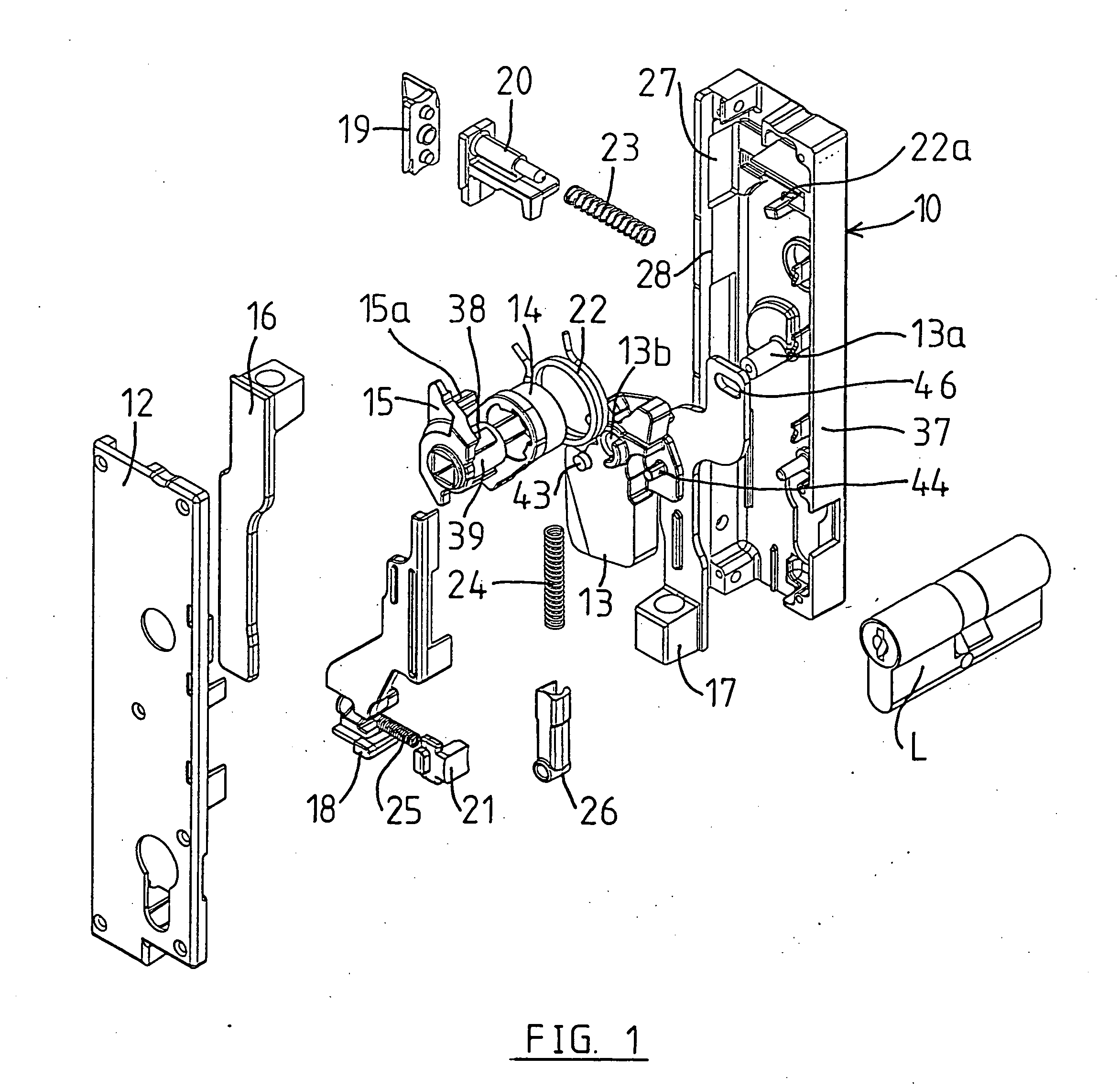
[0035] Referring firstly to FIG. 1 of the drawings, there is shown a multi-point swing door lock in exploded form. This illustrates the componentry of the lock. The components, other than the lock cylinder and spring components are all designed so that they can be manufactured by diecasting from, for example, zinc diecasting material.

[0036] As will be apparent to those skilled in the art from the following description some of the components are multifunctional which provides for a minimum number of component parts. Also as will be apparent from the following description, ease of assembly not only arises from the minimum number of parts but also the use of a modular torsional spring assembly.

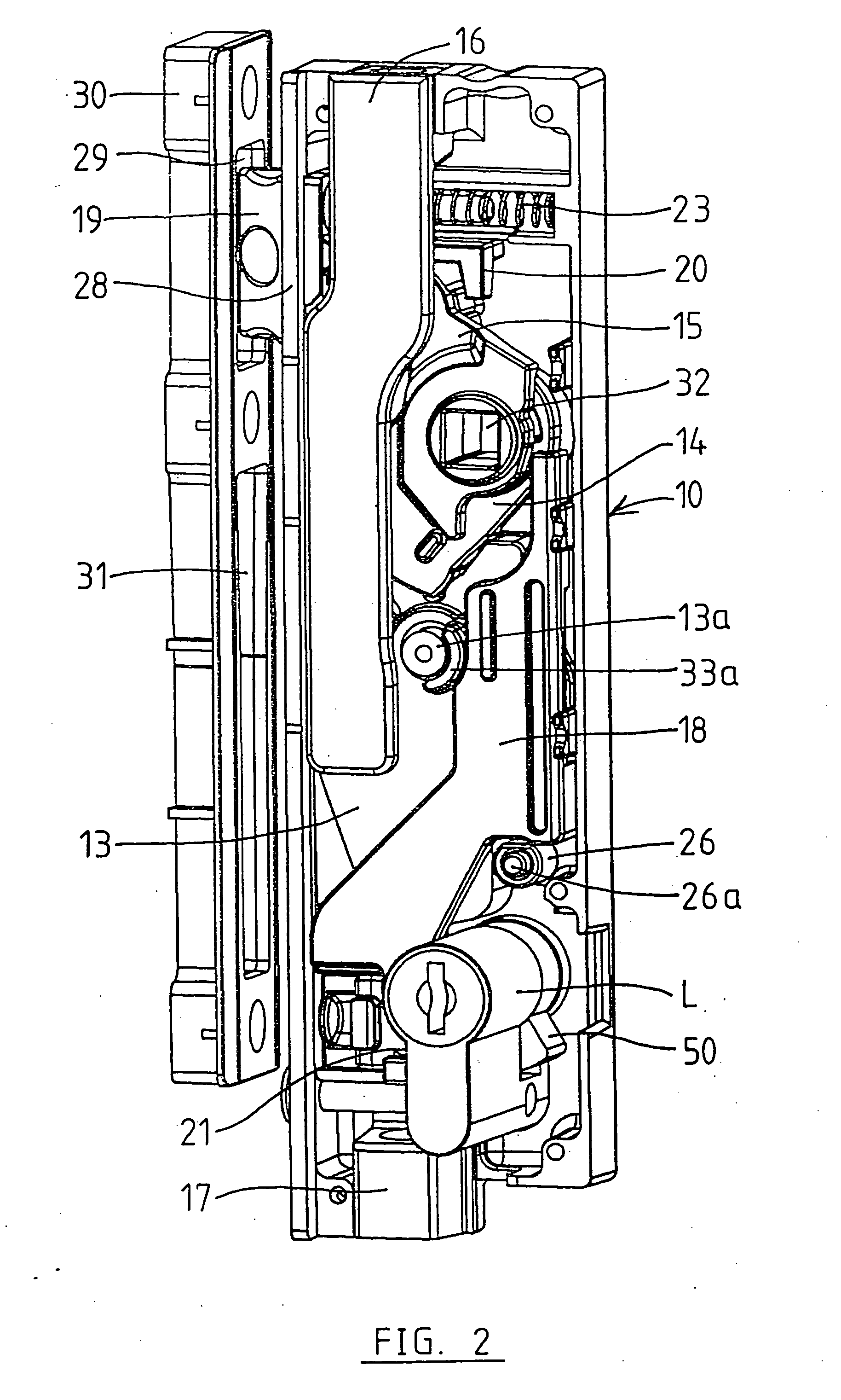
[0037] The lock according to the illustrated form includes a housing 10 on which is fitted a cover 12 once the component parts have been assembled within the housing 10. Pivotally mounted with the housing is a lift bolt or deadbolt 13. This is pivotally mounted by pin 13a, which projects from t...


PUM


Abstract

A multi-point lock for a closure includes two or more of a latch (19,20), lift bolt (13) and at least one drive element (16,17) for operating a shoot bolt or remote deadbolt. A drive cam (15), a drive gear (14) and a toothed member (42) coupled to at least one of said lift bolt (13) and at least one said drive element (16,17), said toothed member (42) being in meshed engagement with the drive gear (14), said drive cam (15) being drivingly coupled with the drive gear (14) via a lost motion coupling (38,40). Rotation of the drive cam (15) in one direction can thus actuate the latch (19,20) and in the opposite direction actuate the drive gear (14) to cause movement of the lift bolt (13) and drive element (16,17).

Description

BACKGROUND TO THE INVENTION [0001] This invention relates to a multi-point lock and more particularly a multi-point lock for a swing door. [0002] Multi-point swing door locks are known. They provide a higher level of security due to the multiple locking points. Locks of this type also assist in maintaining a weather seal around the perimeter of the opening panel in negative pressure conditions. [0003] As is known in the art the multiple locking points can be created by a the latch tongue, a deadbolt and one or more shoot bolts or remotely operated deadbolts. In a preferred form of a multi-point lock there may be two shoot bolts or remote deadbolts, one providing a locking point at an upper edge of the door and the other at a lower edge of the door. With shoot bolts the top shoot bolt will engage in a top cross member of the door frame and the lower shoot bolt into the floor or a lower cross-frame member of the door frame. Similar locking points can be achieved with remote deadbolts ...

Claims


Application Information

Patent Timeline
IPC IPC(8): E05B15/00E05B59/00E05B63/00E05B63/14E05C9/04E05C9/20
CPCE05B15/004E05B59/00E05C9/047E05C9/042E05C9/20E05B63/0013Y10T70/5226
Inventor BOTHA, ANDRIES JOHANNES MARTHINUSTOULIS, CHRISTODOULOSCASTELINO, AJAY MICHAELGOW, ANDREW MURRAY
Owner ASSA ABLOY FINANCIAL SERVICES
Why Eureka
Try Eureka