Accelerated plasma clean

a plasma clean and plasma technology, applied in the field of substrate processing, can solve the problems of high maintenance cost, undetectable film deposition on any hot surface, defective wafers, etc., and achieve the effect of reducing the time required for cleaning the processing chamber

Inactive Publication Date: 2005-05-19
APPLIED MATERIALS INC
View PDF42 Cites 18 Cited by
  • Summary
  • Abstract
  • Description
  • Claims
  • Application Information

AI Technical Summary

Benefits of technology

[0010] The present invention provides a method and apparatus that reduces the time required to clean a processing chamber employing a reactive plasma cleaning technique. Some embodiments of invention do so by employing an Astron fluorine source generator which is in fluid communication with a processing chamber and a supply of fluorine source gas and a supply of inert source gas. In one embodiment, a plasma is formed in the Astron from a flow of substantially pure inert source gas. After formation of the plasma, a flow of a fluorine source gas is introduced therein such that the fluorine source flow accelerates at a rate no greater than 1.67 standard cubic centimeters per second2 (scc / s2). In this fashion, the plasma contains a plurality of radicals and dissociated inert-source gas atoms, defining a cleaning mixture. Forming the plasma in the absence of a fluorine source gas flow overcomes a previously unrecognized problem. Specifically, it was found that flowing a great amount of fluorine source gas into the ASTRON reactive plasma generator would quench the plasma. As a result, the inert-source gas and fluorine source are flowed into the Astron to ensure that the ratio of the former to the latter is greater than 1:1 Specifically, it is believed that the sudden dissociation of the fluorine source gas atoms causes a pressure spike. By slowly accelerating a flow of fluorine source gas into the plasma while ensuring that the aforementioned ratio is satisfied, this problem is overcome.

Problems solved by technology

One problem that arises during such CVD processes is that unwanted deposition occurs in the processing chamber and leads to potentially high maintenance costs.
With CVD of a desired film on a wafer, undesired film deposition can occur on any hot surface including the heater or process kit parts of the apparatus, because the reactive gases can diffuse everywhere in the processing chamber, even within cracks and around corners.
Over time, failure to clean the residue from the CVD apparatus often results in degraded, unreliable processes and defective wafers.
Depending on which and how many parts need replacing and the frequency of the replacement, the cost of maintaining the substrate processing system can become very high.
Failure to periodically wet clean a CVD apparatus results in accumulation of impurities that can migrate onto the wafer and cause device damage.
However, the cleaning procedures reduce the availability of a system for manufacture due to the down-time required to complete the procedures.
What is needed, however, is a reactive plasma cleaning procedure which further reduces the time required to clean a processing chamber, as compared to the prior art.

Method used


Image

  • Accelerated plasma clean
  • Accelerated plasma clean
  • Accelerated plasma clean

Examples


Embodiment Construction

I. Exemplary CVD System

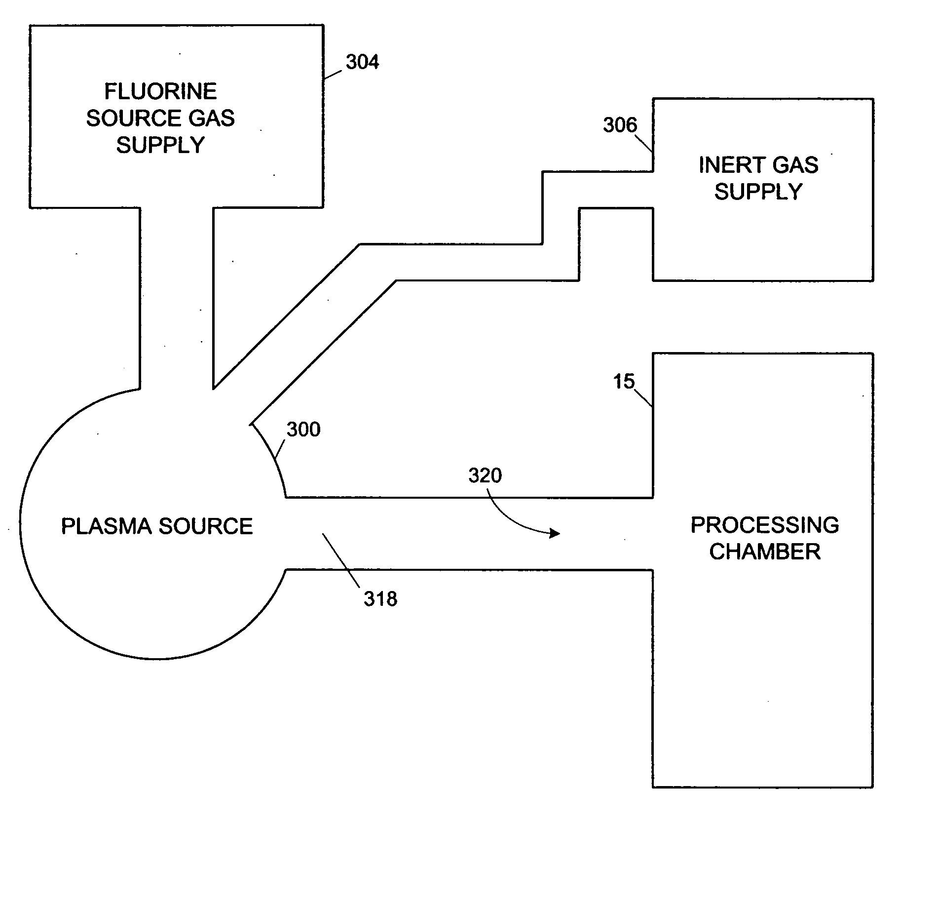
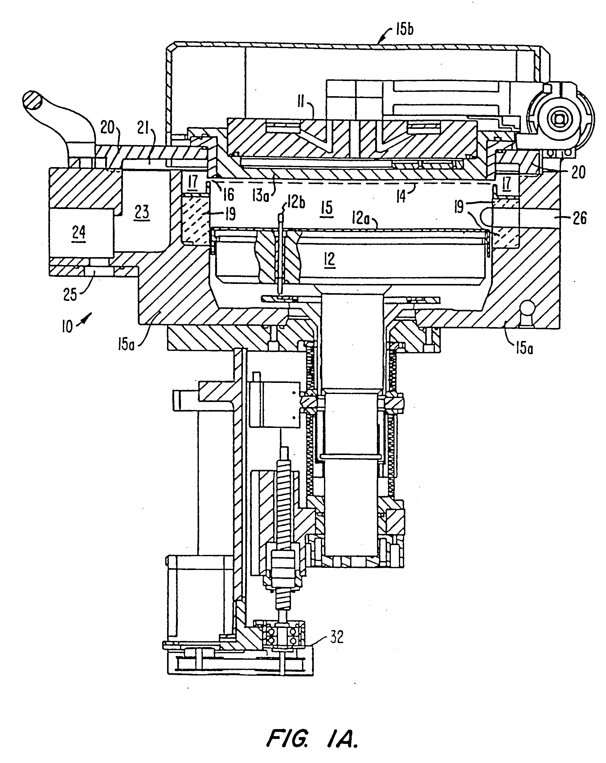
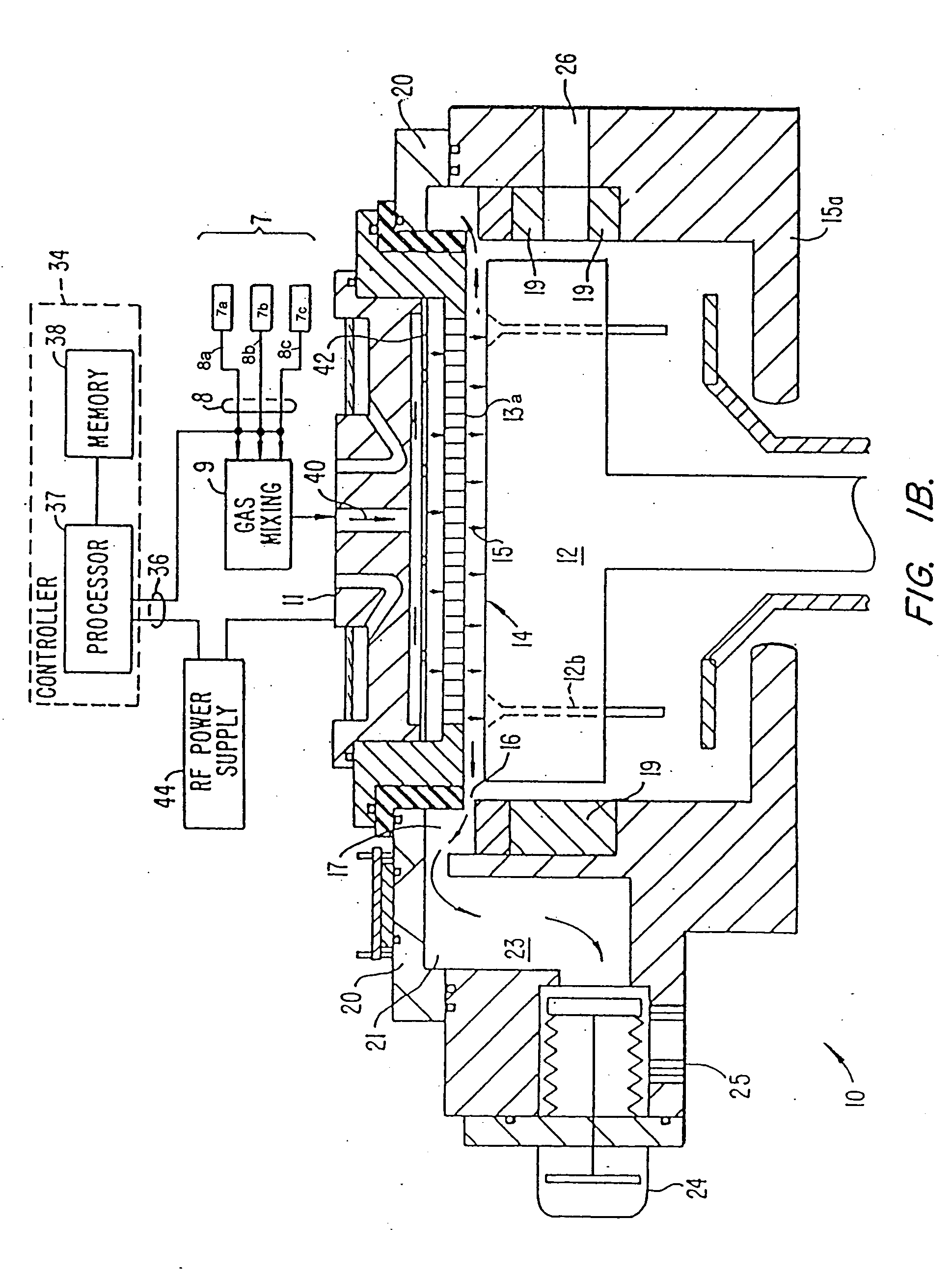
[0023] Specific embodiments of the present invention may be used with or retrofitted onto a variety of chemical vapor deposition (CVD) or other types of substrate processing apparatus. One suitable substrate processing apparatus with which the present invention can be used or retrofitted is shown in FIGS. 1A and 1B, which are vertical, cross-sectional views of a CVD system 10, having a vacuum or processing chamber 15 that includes a processing chamber wall 15a and processing chamber lid assembly 15b. Processing chamber wall 15a and processing chamber lid assembly 15b are shown in exploded, perspective views in FIGS. 1C and 1D.

[0024] Referring to FIGS. 1A, 1B, 1C and 1D, CVD system 10 contains a gas distribution manifold 11 for dispersing process gases to a substrate (not shown) that rests on a resistively-heated pedestal 12 centered within the processing chamber. During processing, the substrate (e.g., a semiconductor wafer) is positioned on a flat (or slight...


PUM

PropertyMeasurementUnit
etch rateaaaaaaaaaa
frequencyaaaaaaaaaa
pressureaaaaaaaaaa

Abstract

A method and apparatus that reduces the time required to clean a processing chamber employing a reactive plasma cleaning process. A plasma is formed in an Astron fluorine source generator from a flow of substantially pure inert-source gas. After formation of the plasma, a flow of a fluorine source gas is introduced therein such that the fluorine source flow accelerates at a rate no greater than 1.67 standard cubic centimeters per second2 (scc/s2). In this fashion, the plasma contains a plurality of radicals and dissociated inert-source gas atoms, defining a cleaning mixture. The ratio of inert-source gas to fluorine source is greater than 1:1.

Description

CROSS-REFERENCES TO RELATED APPLICATIONS [0001] This application is a division of U.S. application Ser. No. 10 / 115,665, filed Apr. 2, 2002, entitled “Accelerated Plasma Clean,” having Shankar N. Chandran, Scott Hendrickson, Gwendolyn D. Jones, Shankar Venkataraman and Ellie Yieh listed as coinventors; which is a division of U.S. application Ser. No. 09 / 246,036, filed Feb. 4, 1999. The disclosures of Ser. Nos. 10 / 115,665 and 09 / 246,036 are herein incorporated herein by reference in their entirety.BACKGROUND OF THE INVENTION [0002] The present invention relates to substrate processing. Specifically, the present invention relates to an apparatus and method for cleaning a processing chamber in a substrate processing system which reduces the time required to complete a dry-clean technique by increasing the flow-rate of cleaning gases therein. [0003] One of the primary steps in the fabrication of modern semiconductor devices is the formation of a layer, such as a metal silicide layer like...

Claims


Application Information

Patent Timeline
Patent Type & Authority Applications(United States)
IPC IPC(8): B08B9/08C23C16/44H01L21/304
CPCC23C16/4405Y10S438/905Y10S134/902H01L21/304
Inventor CHANDRAN, SHANKAR N.HENDRICKSON, SCOTTJONES, GWENDOLYN D.VENKATARAMAN, SHANKARYIEH, ELLIE
Owner APPLIED MATERIALS INC
Why Eureka
Try Eureka