Laser receiver

a laser receiver and receiver technology, applied in the field of laser receivers, can solve the problem that conventional lasers cannot effectively carry out long-distance measurements, and achieve the effect of accurate laser positioning

Inactive Publication Date: 2005-05-19
QUARTON
View PDF8 Cites 13 Cited by
  • Summary
  • Abstract
  • Description
  • Claims
  • Application Information

AI Technical Summary

Benefits of technology

[0009] If the laser is evenly distributed between the two photodetectors, then the laser position will be set as the correct position and a corresponding signal will be displayed. However, if the first photodetector detects more light than the second photodetector, then a signal will also be displayed to inform the user that more laser is bein

Problems solved by technology

Since the distance measured by such visual inspection in a levelling measurement can only cove

Method used


Image

  • Laser receiver
  • Laser receiver
  • Laser receiver

Examples


Embodiment Construction

[0013] The following detailed description is of the best presently contemplated modes of carrying out the invention. This description is not to be taken in a limiting sense, but is made merely for the purpose of illustrating general principles of embodiments of the invention. The scope of the invention is best defined by the appended claims.

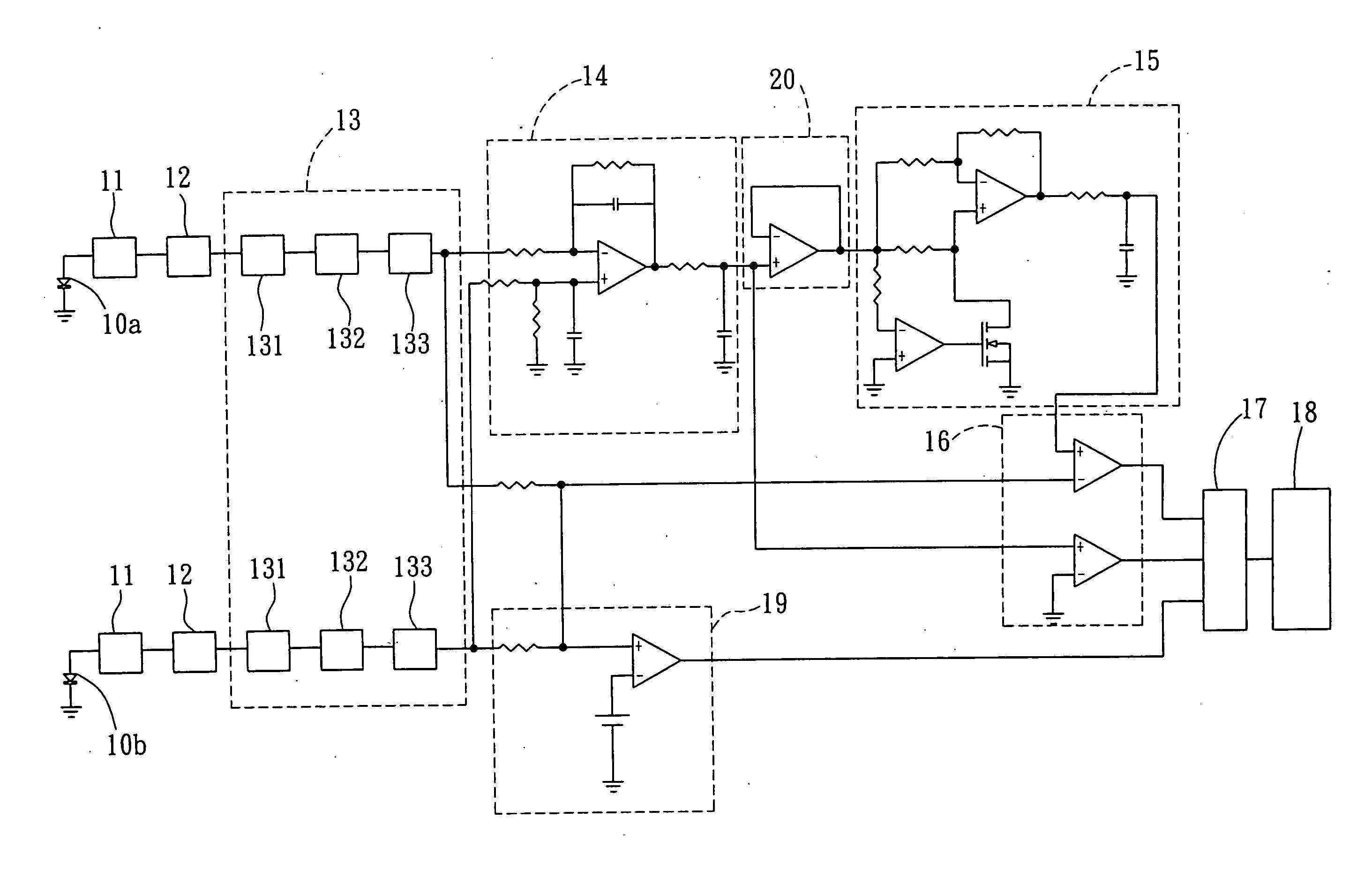
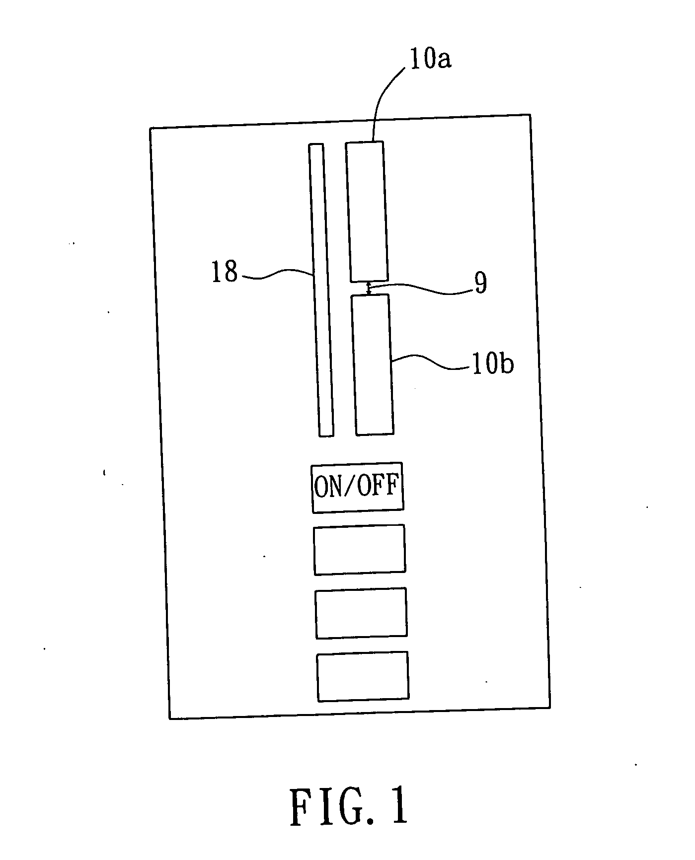
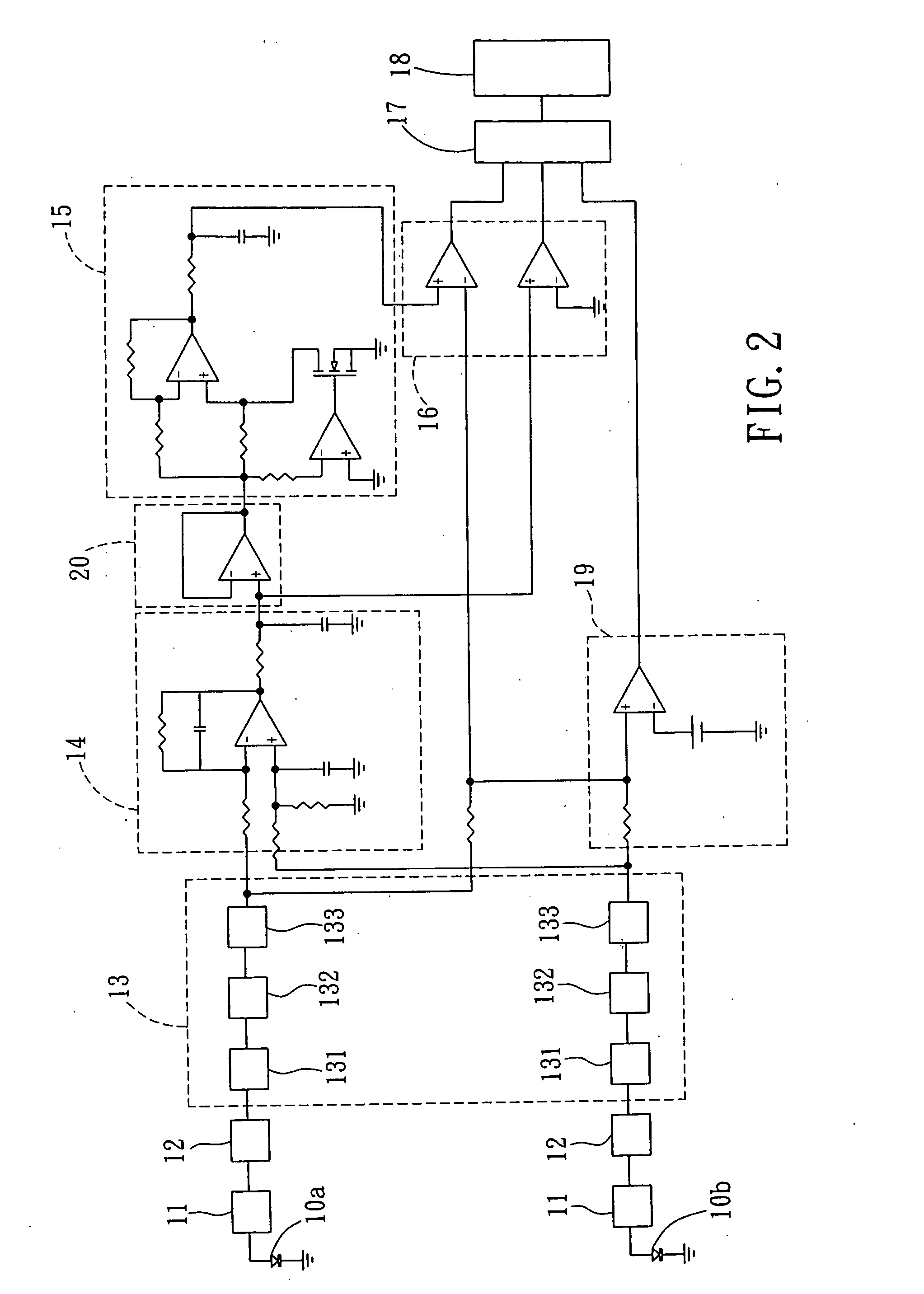
[0014] The laser receiver of the present invention includes a first photodetector and a second photodetector for detecting a laser. If the laser is evenly distributed between the two photodetectors, then the laser position will be set as the correct position and a corresponding signal will be displayed. However, if the first photodetector detects more light than the second photodetector, then a signal will also be displayed to inform the user that more laser is being projected onto the first photodetector. On the other hand, if the second photodetector detects more light than the first photodetector, then a signal will be displayed to inform the...


PUM


Abstract

A laser receiver for detecting the position of incidence of a beam of laser light thereon includes a first photodetector and a second photodetector aligned in series with each other and spaced apart from each other by a gap. If the laser is evenly distributed between the two photodetectors, then the laser position will be set as the correct position and a corresponding signal will be displayed. However, if the first photodetector detects more light than the second photodetector, then a signal will also be displayed to inform the user that more laser is being projected onto the first photodetector. On the other hand, if the second photodetector detects more light than the first photodetector, then a signal will be displayed to inform the user that more laser being projected onto the second photodetector. These signals will assist users to adjust the laser receiver to accurately position the laser.

Description

BACKGROUND OF THE INVENTION [0001] 1. Field of the Invention [0002] The present invention relates to a laser receiver, and more particularly, to a laser receiver for detecting the position of incidence of a beam of laser light thereon. [0003] 2. Description of the Prior Art [0004] Laser technology has become very popular in recent times. Laser has major advantages due to its high power, monochromaticity, collimation, and coherence. Therefore, laser is generally used in research and development, medical treatment, communication, information, and other industrial areas, not only benefiting people, but also promoting the overall development of related industries. [0005] Lasers are commonly being used for long-distance measurements, such as a level measurement which makes use of the specific frequency of the laser for positioning. A laser is emitted, and the position of the laser is inspected visually. Since the distance measured by such visual inspection in a levelling measurement can ...

Claims


Application Information

Patent Timeline
IPC IPC(8): G01C15/00G01J1/42
CPCG01J1/4257G01C15/006
Inventor HSIAO, CHING-HORNG
Owner QUARTON
Why Eureka
Try Eureka