

Piezoelectric device, cellular phone system using the piezoelectric device, and electronic equipment using the piezoelectric device
- Summary
- Abstract
- Description
- Claims
- Application Information
AI Technical Summary
Benefits of technology
Problems solved by technology
Method used
Image

Examples
first embodiment
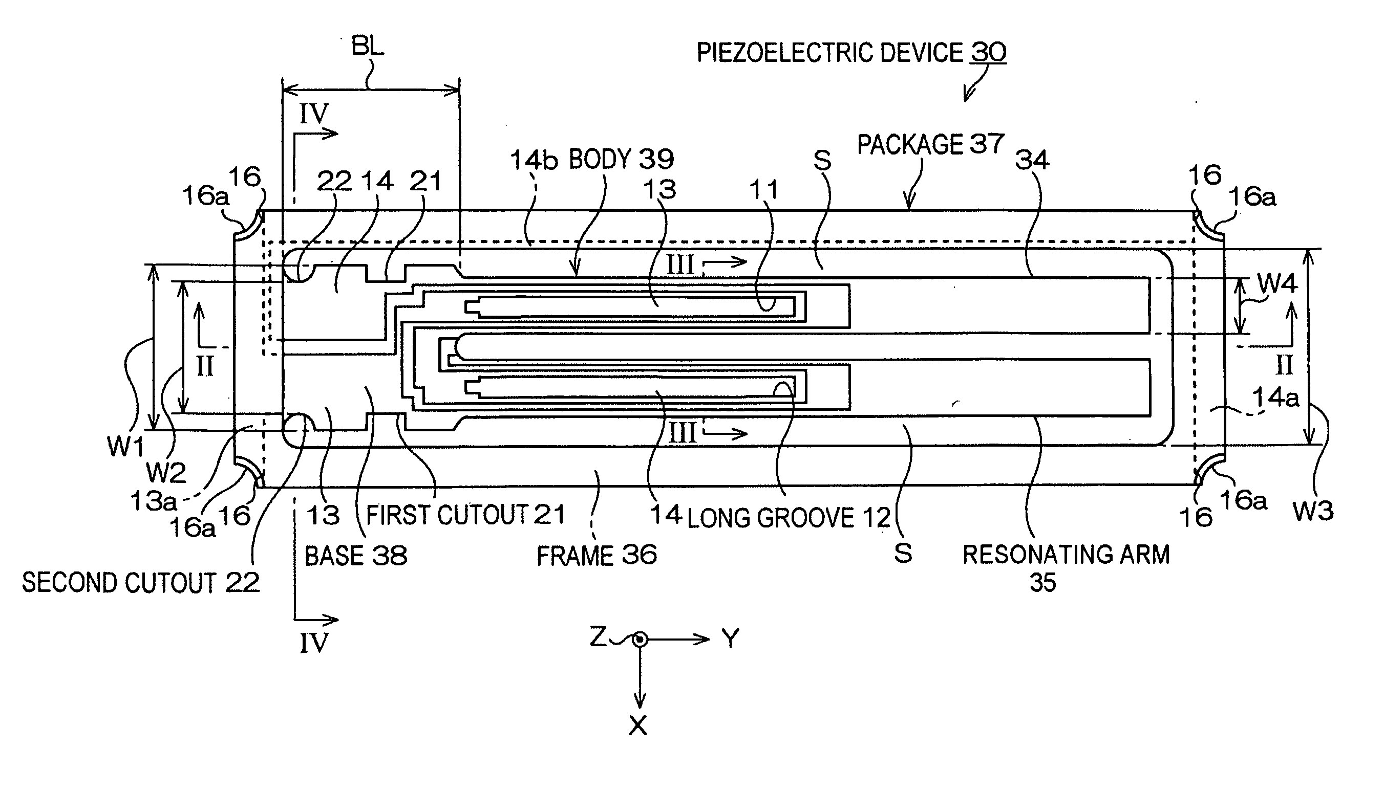
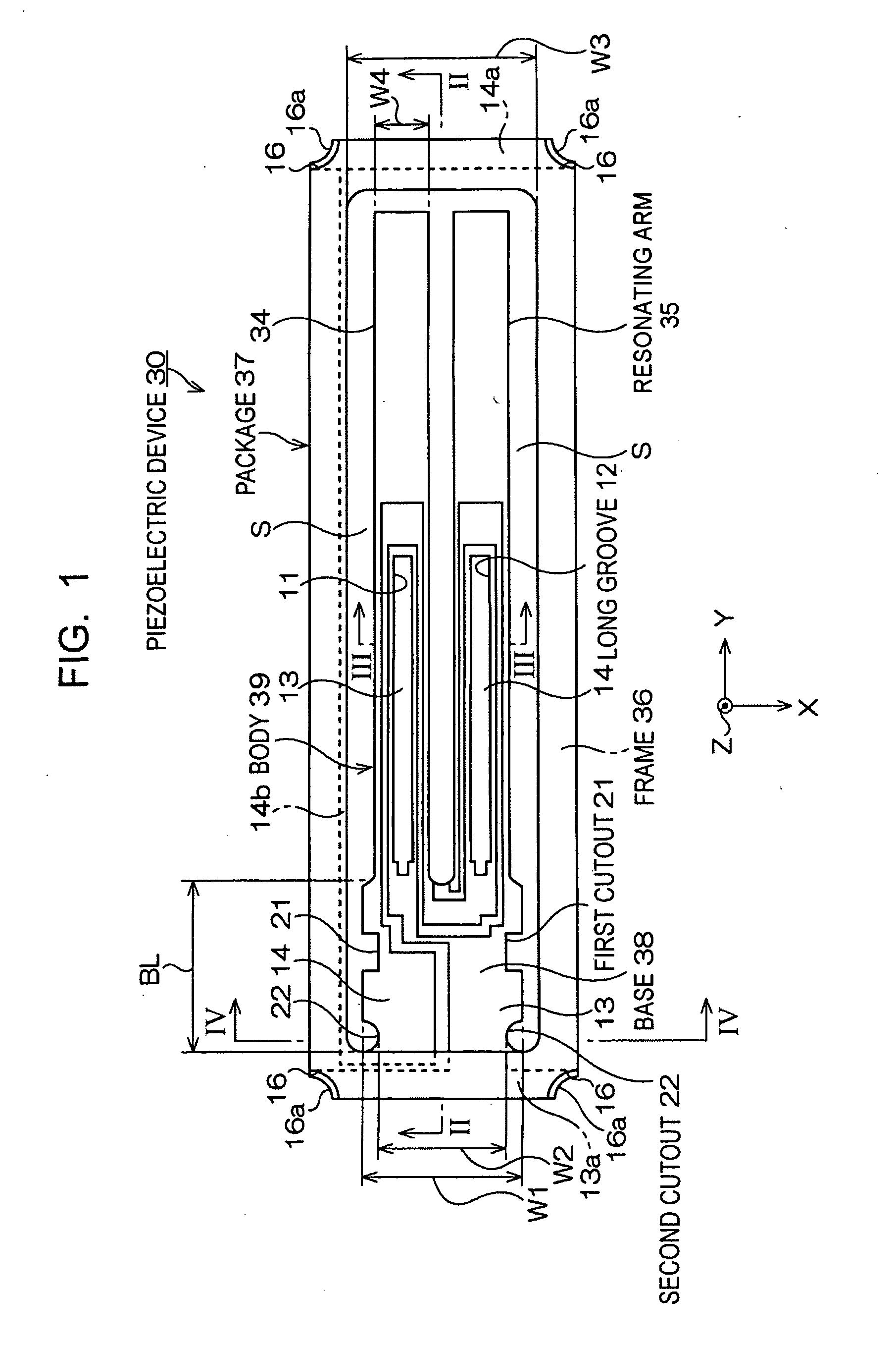
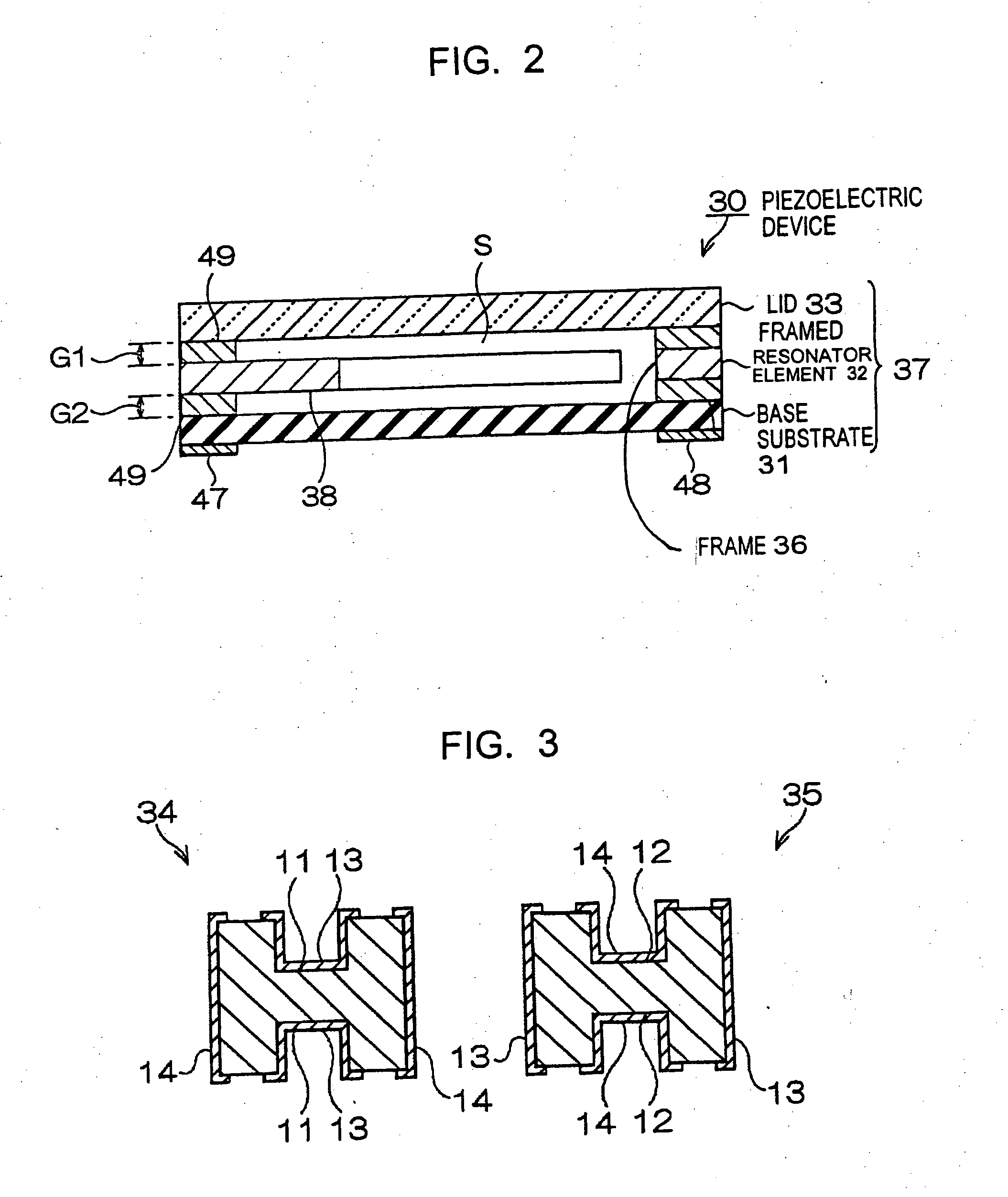
[0050] FIGS. 1 to 3 show a piezoelectric device according to the present invention. FIG. 1 is a schematic plan view of the piezoelectric device, FIG. 2 is a schematic cross-sectional view thereof taken along line II-II in FIG. 1, and FIG. 3 is a sectional end view thereof taken along line III-III in FIG. 1.
[0051] Referring to FIGS. 1 to 3, a piezoelectric device 30 constitutes a piezoelectric transducer. The piezoelectric device 30 has a resonator element housed in a package 37.
[0052] Specifically, the piezoelectric device 30 has a base substrate 31, a framed resonator element 32 that is fixed on the base substrate 31, and a lid 33 that is layered and fixed on the framed resonator element 32.
[0053] In the piezoelectric device 30, the package 37 for hermetically housing the resonator element is structured so as to include the base substrate 31, the frame of the framed resonator element 32, and the lid 33. In other words, layering the lid 33 on the framed resonator element 32 that i...
second embodiment
[0078]FIGS. 6 and 7 show a piezoelectric device according to the present invention. FIG. 6 is a schematic plan view of the piezoelectric device and FIG. 7 is a schematic cross-sectional view thereof taken along line VII-VII in FIG. 6.
[0079] The same reference numerals are used in FIGS. 6 and 7 to identify the same components as in the piezoelectric device 30 of the first embodiment. A duplicated description is omitted here and only differences are mainly described.
[0080] A piezoelectric device 60 of the second embodiment is structured so as to house the framed resonator element 32 in the first embodiment in a package 37-1.
[0081] The package 37-1, made of an insulating material, is a rectangular box. For example, a first substrate 51, a second substrate 52, and a third substrate 53 are sequentially layered to form the package 37-1. A through-hole 43 is formed near the center of the package 37-1. The first substrate 51 and the second substrate 52 constitute a base substrate. The thr...
third embodiment
[0087]FIGS. 8 and 9 show a piezoelectric device according to the present invention. FIG. 8 is a schematic plan view of the piezoelectric device and FIG. 9 is a schematic cross-sectional view thereof taken along line IX-IX in FIG. 8.
[0088] The same reference numerals are used in FIGS. 8 and 9 to identify the same components in the piezoelectric device 30 of the first embodiment and the piezoelectric device 60 of the second embodiment. A duplicated description is omitted here and only differences are mainly described.
[0089] A piezoelectric device 70 of the third embodiment is structured so as to house a framed resonator element 72 in the package 37-1, as in the second embodiment.
[0090] The piezoelectric device 70 of the third embodiment differs from the piezoelectric device 60 of the second embodiment in the structure of the framed resonator element 72. A framed resonator element part 36-1 of the framed resonator element 72 is not provided around the resonator element body 39, but i...
PUM
 Abstract
Description
Claims
Application Information