
Rotation angle-detecting device

Inactive Publication Date: 2005-05-19
PANASONIC CORP
View PDF5 Cites 6 Cited by
  • Summary
  • Abstract
  • Description
  • Claims
  • Application Information

AI Technical Summary

Benefits of technology

[0005] The rotation angle-detecting device of the present invention contains a first detecting rotator; a second detecting rotator; a first magnet; a second magnet; a first magnetic detector; a second magnetic detector; a ferromagnetic body encircling any one of the first and the second magnets and the first and the second magnetic detectors; and a calculator. Having a mesh engagement with the main rotator, the first detecting rotator rotates at a speed higher than the main rotator

Problems solved by technology

According to the conventional rotation angle-detecting device, however, the first gear through which a steering shaft is fitted has a large diameter, accordingly, the diameter of a bearing inevitably becomes large.
Therefore, the first gear tends to have a distortion.
The loose fit brings a relatively large play between the second and the third gears, and therefore, an error of measurement occurs in the two sensors in evaluating an absolute angle.
As another inconvenience in the conventional structure, in reducing the size of the device, the magnets built in the second and the third gears interfere magnetic lines with each other, thereby degrading the accuracy in determining the rotation angle.

Method used


Image

  • Rotation angle-detecting device
  • Rotation angle-detecting device
  • Rotation angle-detecting device

Examples


Embodiment Construction

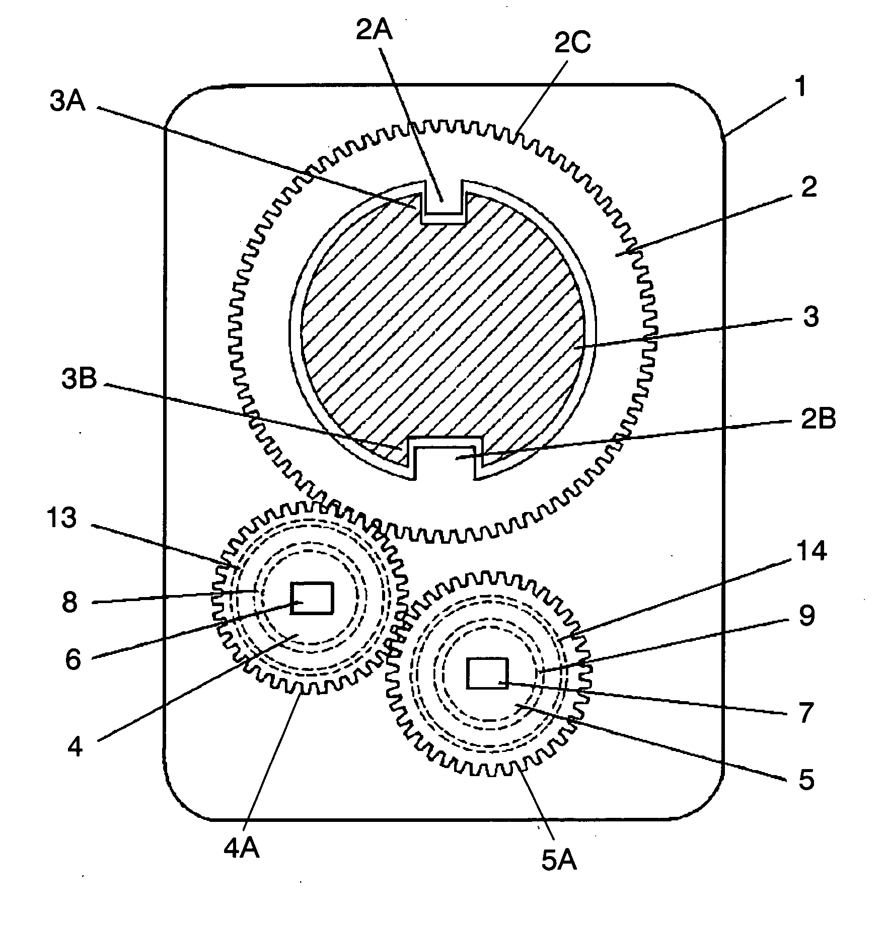
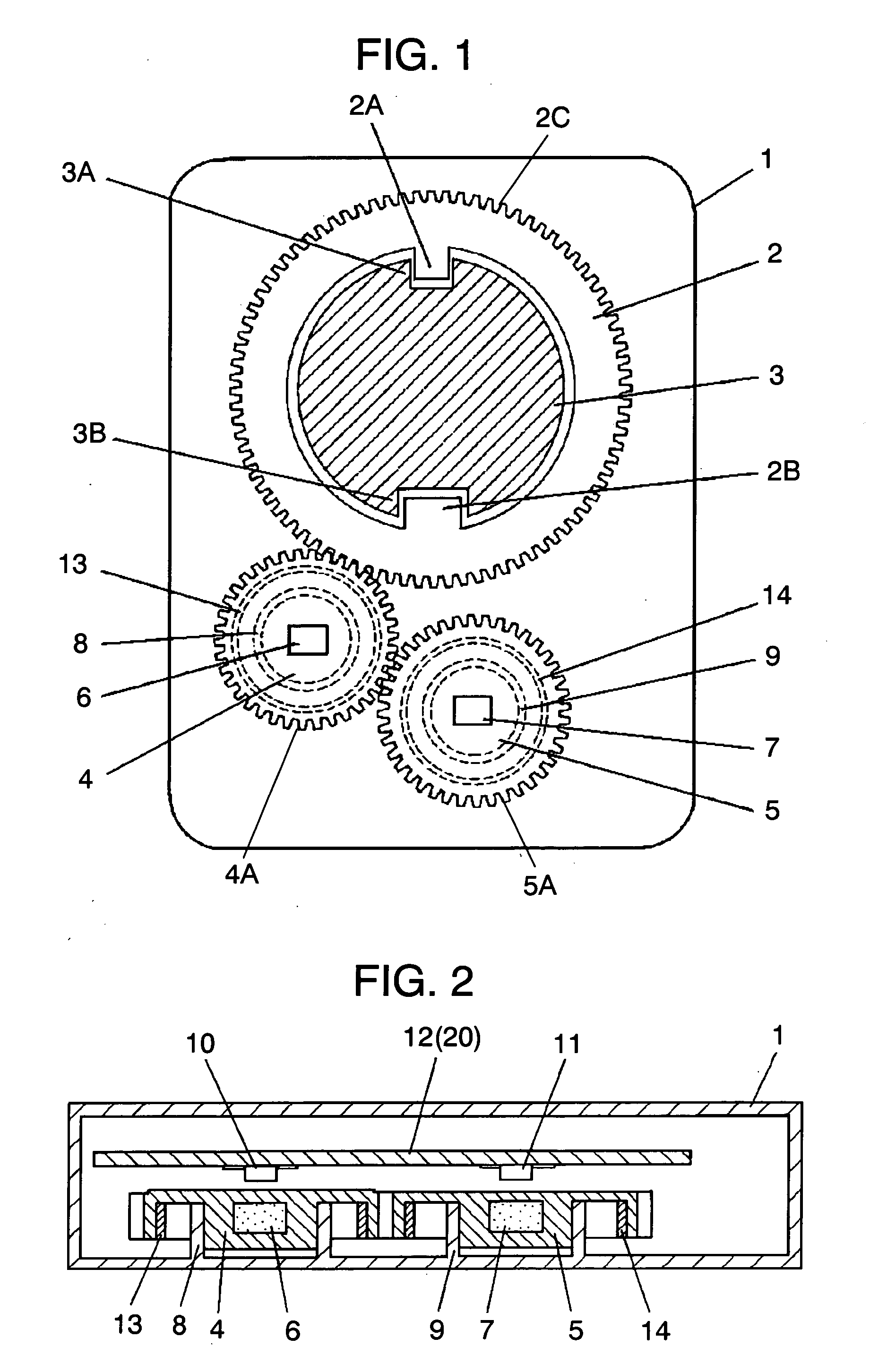
[0025]FIG. 1 shows the structure of a rotation angle-detecting device of an exemplary embodiment of the present invention. FIG. 2 is a side sectional view of the rotation angle detecting section of the device. Main rotator 2 has gear 2C on its perimeter. Steering shaft 3 runs through the center of main rotator 2. Projections 2A and 2B of main rotator 2 are fitted in grooves 3A and 3B, respectively, of steering shaft 3. Rotatably fixed around bearing 8, first detecting rotator (hereinafter referred to as rotator) 4 has gear 4A on its perimeter. Gear 4A has a meshing engagement with gear 2C of main rotator 2. Rotator 4 has a diameter smaller than that of main rotator 4, that is, rotator 4 rotates faster than main rotator 2. Similarly, second detecting rotator (hereinafter, rotator) 5 is rotatably fixed around bearing 9. Gear 5A, which is formed on the perimeter of rotator 5, has a meshing engagement with the gear of rotator 4. Rotator 5 has a diameter slightly larger than that of rota...


PUM


Abstract

The rotation angle-detecting device has a main rotator and two detecting rotators that rotate as the main rotator rotates. Each of the two detecting rotators has a magnet and a magnetic detector. As the detecting rotator rotates, a change occurs in magnetic lines of force from the magnet. From the change, the magnetic detector detects rotation of the detecting rotator. According to the rotation detected, the device determines the rotation angle of the main rotator. In addition, a ring-shaped ferromagnetic body is disposed around the magnet or the magnetic detector of the detecting rotator. The structure described above enables magnetic detection without disturbance in each magnetic field of the magnets, and even in a downsized structure, the device can detect the rotation angle with high accuracy.

Description

TECHNICAL FIELD [0001] The present invention relates to a device for detecting a rotation angle of a steering wheel, employed for a control system and the like in an automobile. BACKGROUND ART [0002] Japanese translation of PCT publication No. H11-500828 introduces a detector for detecting a rotation angle of a main rotator, such as a steering wheel of an automobile that rotates beyond 360° within a predetermined rotation range. The conventional detector contains a first gear fitted with the main rotator and at least two rotators, i.e., a second rotator and a third rotator that cooperate with the first gear. The second and the third rotators have a second and a third gears, respectively. Each sensor for the second and the third rotators detects each rotation angle of the two rotators, and from the phase difference between the second and the third rotators, the rotation angle of the main rotator is found. [0003] According to the conventional rotation angle-detecting device, however, ...

Claims


Application Information

Patent Timeline
IPC IPC(8): G01B7/00G01B7/30G01D5/04G01D5/14G01D5/16G01D5/18
CPCG01D5/145G01D5/04
Inventor USHIHARA, MASAHARUOIKE, KOUJI
Owner PANASONIC CORP
Features
  • Generate Ideas
  • Intellectual Property
  • Life Sciences
  • Materials
  • Tech Scout
  • Unparalleled Data Quality
  • Higher Quality Content
  • 60% Fewer Hallucinations
Learn More