Sensor for determining the angular position of a radiating point source in two dimensions and method of operation

a technology of a point source and a sensor, which is applied in the direction of navigation instruments, instruments for comonautical navigation, instruments, etc., can solve the problems of not providing immunity from errors and not yielding sufficient resolution

Inactive Publication Date: 2005-05-19
ASCENSION TECH
View PDF11 Cites 84 Cited by
  • Summary
  • Abstract
  • Description
  • Claims
  • Application Information

AI Technical Summary

Benefits of technology

[0012] It is a still further object of the present invention to provide such frequency patterns including use of low frequencies followed by variable frequencies followed by high frequencies.
[0013] It is a still further object of the present invention to provide such a sensor in which coarse measurements of position may be carried out through measurements of frequency changes in the variable frequencies and medium and fine position meas

Problems solved by technology

A drawback of such a system is that it does not provide immunity from errors resulting from reflections, and does not yield s

Method used


Image

  • Sensor for determining the angular position of a radiating point source in two dimensions and method of operation
  • Sensor for determining the angular position of a radiating point source in two dimensions and method of operation
  • Sensor for determining the angular position of a radiating point source in two dimensions and method of operation

Examples


first embodiment

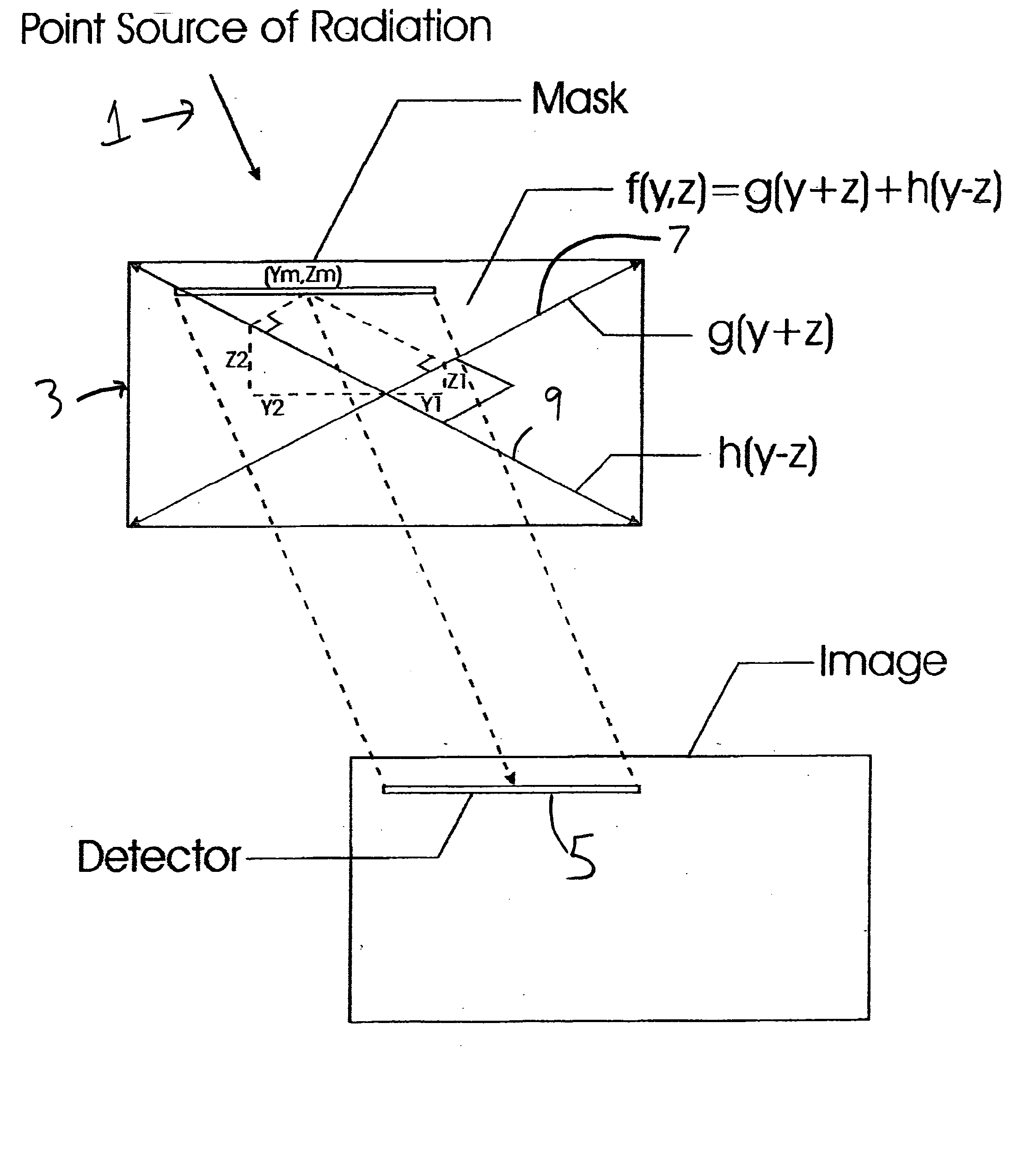
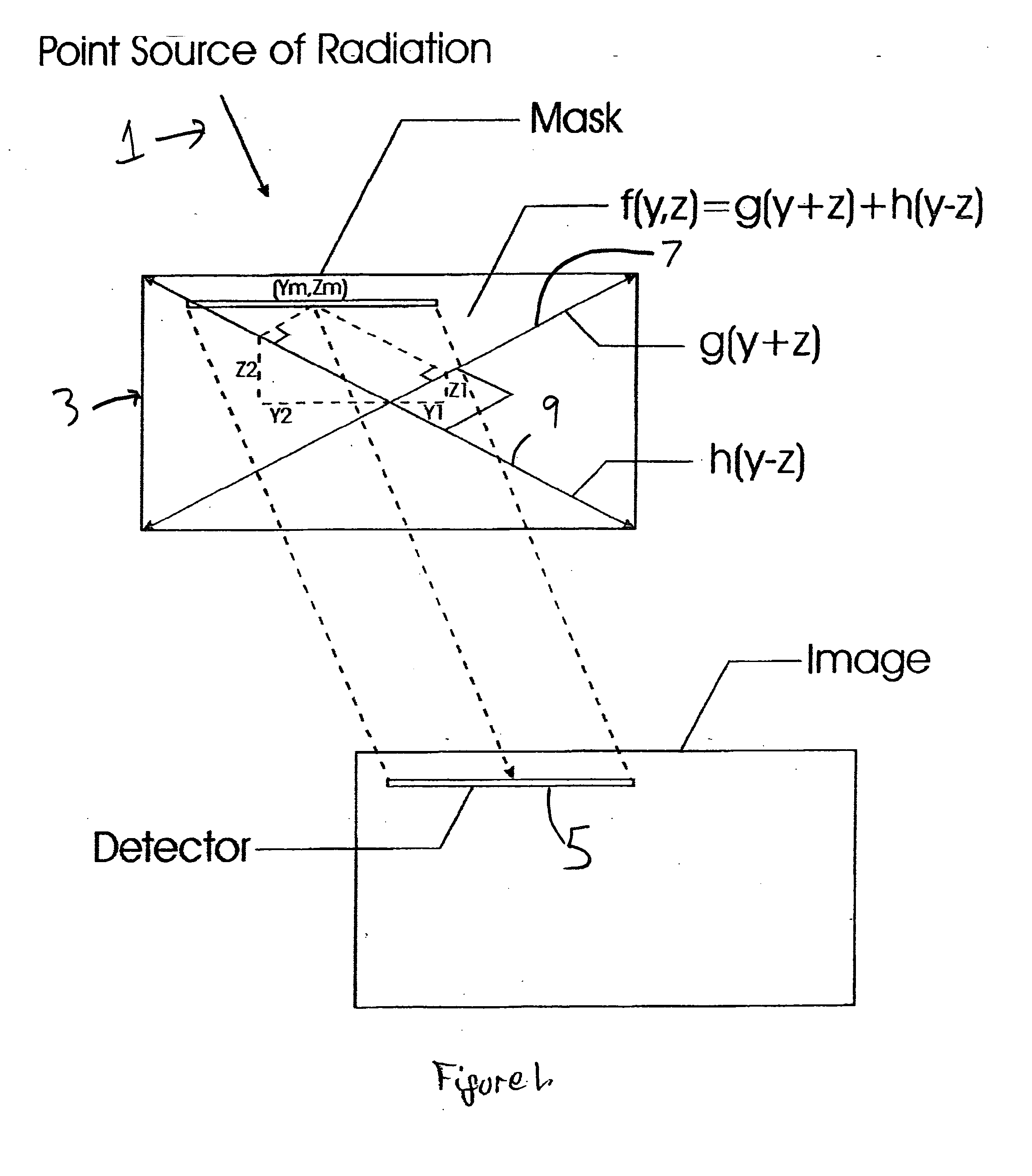
[0024] Reference is first made to FIG. 1 which shows a schematic representation of the present invention. In FIG. 1, a point source of radiation 1 is directed toward a mask 3. The radiation travels through the mask 3 and, as modified by the mask 3, is received by the detector 5.

[0025] With further reference to FIG. 1, the mask 3 has a pattern thereon which is created by a first set of frequencies along the double-headed arrow 7 and a second set of frequencies along the double-headed arrow 9.

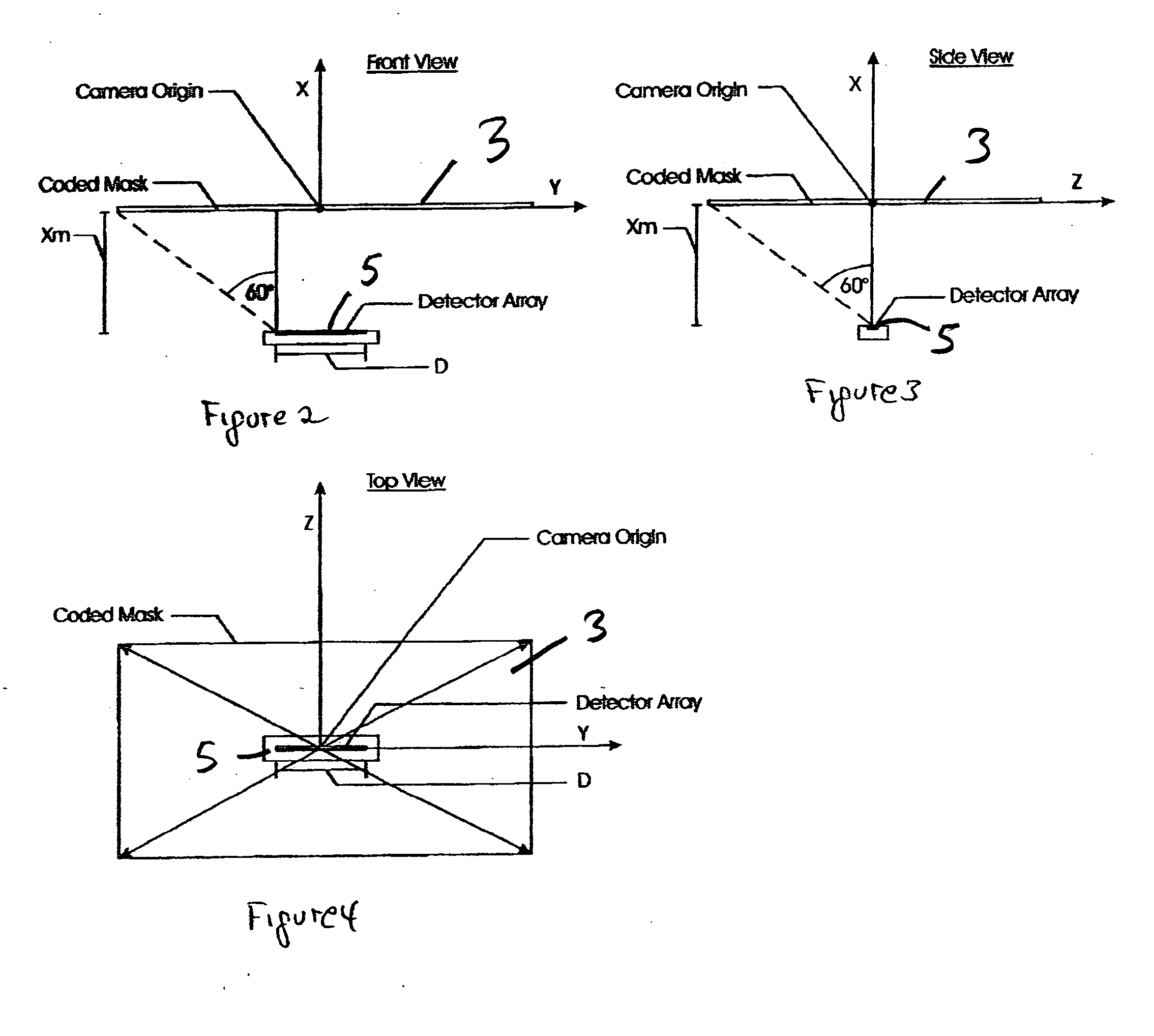
[0026]FIGS. 2, 3 and 4 show front, side and top views, respectively, of the system illustrated in FIG. 1. FIGS. 5, 6 and 7 provide a better understanding of the frequency sequences shown at the reference numerals 7 and 9. Each of the frequency sequences consist of at least two low fixed frequencies followed by at least two variable frequencies followed by at least two fixed high frequencies.

[0027] The detector 5 may, if desired, consist of a linear CCD detector with the mask 3 situated at a pre...

second embodiment

[0039] the present invention is schematically illustrated in FIG. 10. In FIG. 10, the system 10 is seen to include a point source of radiation 11, a mask 3, and a detector 5. The mask 3 has a pattern thereon including fixed low frequency, variable frequency, and fixed high frequency components oriented along the X axis and referred to in FIG. 10 by the function h(y). The mask 3 also has another pattern component oriented along the line Y=Z and referred to by the function g(y+z) which line is designated by the reference numeral 16 and is seen to extend diagonally across the mask 3. That component has fixed low and high frequency components. Additionally, a variable frequency component extends along the Z axis and is designated by the reference numeral 18 as well as by the function j(y,z). That component comprises a variable frequency component.

[0040] For this embodiment, the mask transmissivity function is:

Mask(y,z)=g(y+z)+h(y)+j(y,z)   (22)

Replacing g(y+z), h(y), and j(y,z) by th...


PUM


Abstract

A sensor for determining the angular position of a radiating point source in two dimensions includes a mask encoded in two skewed directions with waveforms consisting of several frequencies in prescribed patterns. The frequency spectra of the received detector patterns are computed. In order to facilitate such computations, the constituent frequencies are separated so as to be distinguished in the Fast Fourier Transform (FFT). Each of the frequency patterns that are coded on the variable transmissivity mask consists of a series of low frequencies followed by a series of variable frequencies, and a series of high frequencies. The variable frequencies exhibit frequency changes responsive to various image positions. The low and high frequencies are responsive in phase to variations in image position. The frequency variations in the variable frequencies are used to indicate coarse position while the phases of the fixed low and high frequencies are used to indicate medium and fine position. In a second embodiment, the mask pattern is formed by a first pattern including low variable and high frequency components, a second pattern with fixed low and high frequency components, and a third pattern with variable frequency components. The method of determining position is also disclosed.

Description

BACKGROUND OF THE INVENTION [0001] The present invention relates to a sensor for determining the angular position of a radiating point source in two dimensions and its method of operation. The present invention has particular pertinence in the field of surgery, with particular reference to close range surgical instrument tracking. Additionally, the present invention is applicable in the fields of virtual reality and pilot head tracking systems. [0002] In the prior art, systems have been devised that employ one dimensional masked or coded apertures placed above multi-element one dimensional detectors. Such structure is disclosed in U.S. Pat. Nos. 4,810,870 and 5,408,323. In such systems, correlation techniques are employed to determine the position of a projected pseudo-random pattern on a detector surface by comparing signals from fixed detector elements arranged in a unique pattern or from comparison with fixed reference signals previously stored in a computer. [0003] Additionally,...

Claims


Application Information

Patent Timeline
IPC IPC(8): A61B19/00G01D5/347G06T7/00
CPCA61B19/52A61B19/5244A61B2019/5437A61B2019/5445G01S3/781G01D5/347G01D5/3473G06T7/004G01D5/34A61B34/20A61B90/36A61B2090/3937A61B2090/3945G06T7/70G01D2205/90
Inventor DULING, ALECODELL, DON
Owner ASCENSION TECH
Why Eureka
Try Eureka