Method and apparatus coupling at least one piezoelectric device to a slider in a hard disk drive for microactuation
Active Publication Date: 2005-05-19
SAMSUNG ELECTRONICS CO LTD
View PDF32 Cites 56 Cited by
Summary
Abstract
Description
Claims
Application Information
AI Technical Summary
This helps you quickly interpret patents by identifying the three key elements:
Problems solved by technology
Method used
Benefits of technology
[0011] The invention provides a cost effective, reliable region supporting piezoelectric devices that may be used for micro-actuation in hard disk drives. The region couples to a slider by the slider mounting face, and couples to the piezoelectric device by the offset mounting face. The piezoelectric device preferably couples to the offset mounting face by coupling with the first contact region and the second contact region. When the piezoelectric de
Problems solved by technology
However, increasing servo bandwidth is difficul
Method used
Image
Click on the blue label to locate the original text in one second.
Reading with bidirectional positioning of images and text.
Examples
Embodiment Construction
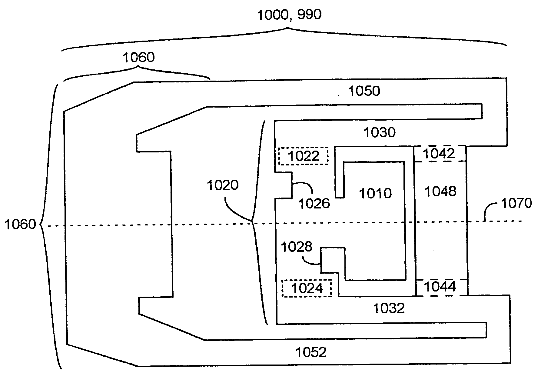
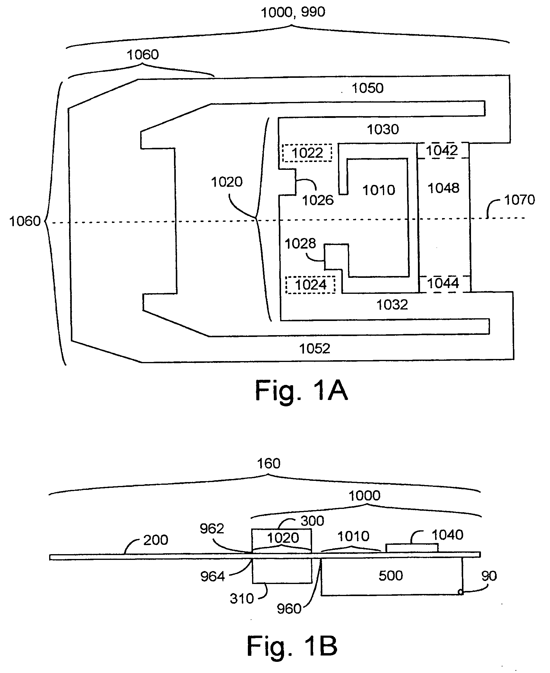
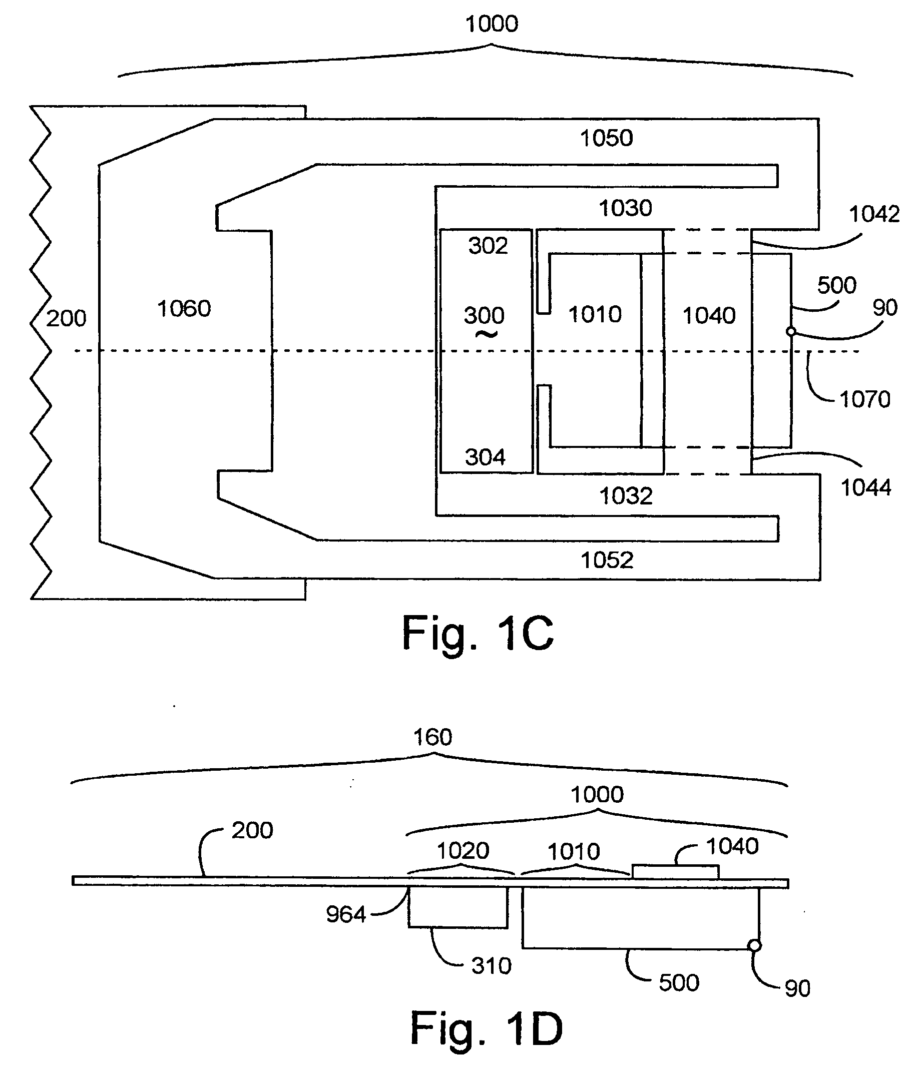
[0032] The invention includes a region of a flexure layer, including the following. A slider mounting face coupled to an offset mounting face for at least one piezoelectric device. The offset mounting face for the piezoelectric device provides an asymmetry between a first contact region and a second contact region. The flexure layer is primarily composed of a stiff material. The stiff material is preferably a form of stainless steel. Alternatively, the stiff material may have comparable or greater stiffness than stainless steel. The stiff material may be primarily composed of a metallic alloy. The metallic alloy may include iron, titanium and / or platinum. Alternatively, the stiff material may include a form of at least one hydrocarbon. A hydrocarbon may include at least one carbon atom and at least one hydrogen atom in a molecular bonding arrangement. The molecular bonding arrangement may implement a lattice of nano-tubes.
[0033] The invention provides a cost effective, reliable reg...
PUM
Abstract
A region of flexure layer, including slider mounting face coupled to offset mounting face for at least one piezoelectric device. The offset mounting face for piezoelectric device provides asymmetry between first contact region and second contact region. This is cost effective, reliable support for piezoelectric devices used for micro-actuation in hard disk drives. The slider moves based upon asymmetry of the offset mounting face coupled to the piezoelectric device twisting the slider mounting face. The invention includes flexure containing the region of the flexure layer. The invention includes head gimbal assembly including flexure, actuator arm including head gimbal assembly, and actuator assembly including actuator arm, and hard disk drive including actuator assembly. The invention includes manufacturing the region, the flexure, the head gimbal assembly, the actuator arm, the actuator assembly and the hard disk drive, as well as these products of the manufacturing processes.
Description
CROSS REFERENCE TO RELATED APPLICATIONS [0001] This application is a continuation in part of application Ser. No. 10 / 007,259, filed Dec. 5, 2001, application Ser. No. 10 / 101,809, filed Mar. 19, 2002, application Ser. No. 10 / 713,616, filed Nov. 13, 2003, application Ser. No. 10 / 903,730, filed Jul. 29, 2004, and application Ser. No. 10 / 757,238, filed Jan. 13, 2004. This application also claims the benefit of U.S. Provisional Application No. 60 / 530,712, filed Dec. 18, 2003. All of the applications set forth above are incorporated herein by reference.TECHNICAL FIELD [0002] The invention relates to the coupling of the slider with at least one piezoelectric device for positioning the slider over a rotating disk surface within a hard disk drive. BACKGROUND OF THE INVENTION [0003] Hard disk drives include a servo-controller driving a voice coil actuator to position a read-write head near a track on a rotating disk surface. The read-write head communicates with the servo-controller, providin...
Claims
Application Information
Patent Timeline
Application Date:The date an application was filed.
Publication Date:The date a patent or application was officially published.
First Publication Date:The earliest publication date of a patent with the same application number.
Issue Date:Publication date of the patent grant document.
PCT Entry Date:The Entry date of PCT National Phase.
Estimated Expiry Date:The statutory expiry date of a patent right according to the Patent Law, and it is the longest term of protection that the patent right can achieve without the termination of the patent right due to other reasons(Term extension factor has been taken into account ).
Invalid Date:Actual expiry date is based on effective date or publication date of legal transaction data of invalid patent.