System for management of Internet telephony equipment deployed behind firewalls

a technology for internet telephony equipment and firewalls, applied in the direction of digital transmission, electrical equipment, transmission, etc., can solve the problems of not allowing any global internet entity in the nat system, unable to deploy such a large number of distribution agents, and unable to expand the total number of devices that the nms can manage without distribution agents

Inactive Publication Date: 2005-05-19
INNOMEDIA PTE
View PDF61 Cites 53 Cited by
  • Summary
  • Abstract
  • Description
  • Claims
  • Application Information

AI Technical Summary

Benefits of technology

[0019] Each TCP/IP connection, established with a client through the firewall serving such client, is established in response to receiving a connection request initiated by such client. An identification of each TCP/IP connection is recorded in an open connections table in association with a client identifier which identifi

Problems solved by technology

A NAT system does not allow any global Internet entity to connect to any private LAN entity unless the NAT system is configured with specific connection rules to enable certain LAN entities to operate as servers for clients outside the LAN.
A challenge with use of the SNMP protocols on a private network with private network IP addresses is that the messages may only be sent to an agent if the NMS is on the same LAN such that the agent's private network IP address is routable.
An NMS on the global side of a NAT system can-not manage an agent on the private network side of the NAT system utilizing the messaging protocols discussed above because it can-not reach the entities with private network addresses.
A first problem with existing hierarchical solutions is that they require that a distribution agent to be present on each LAN on which a managed agent is located.
Deploying such a large num

Method used


Image

  • System for management of Internet telephony equipment deployed behind firewalls
  • System for management of Internet telephony equipment deployed behind firewalls
  • System for management of Internet telephony equipment deployed behind firewalls

Examples


Embodiment Construction

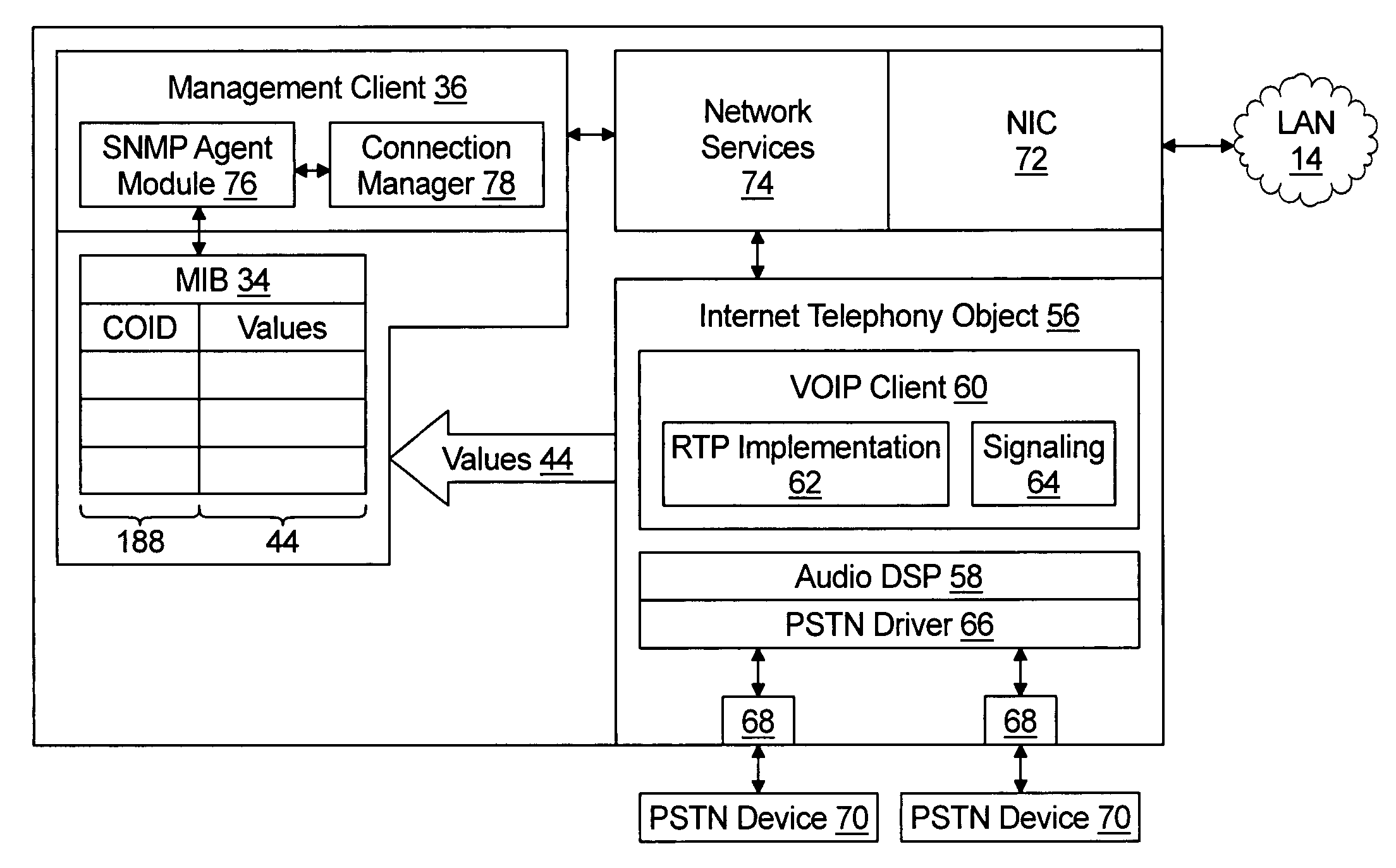
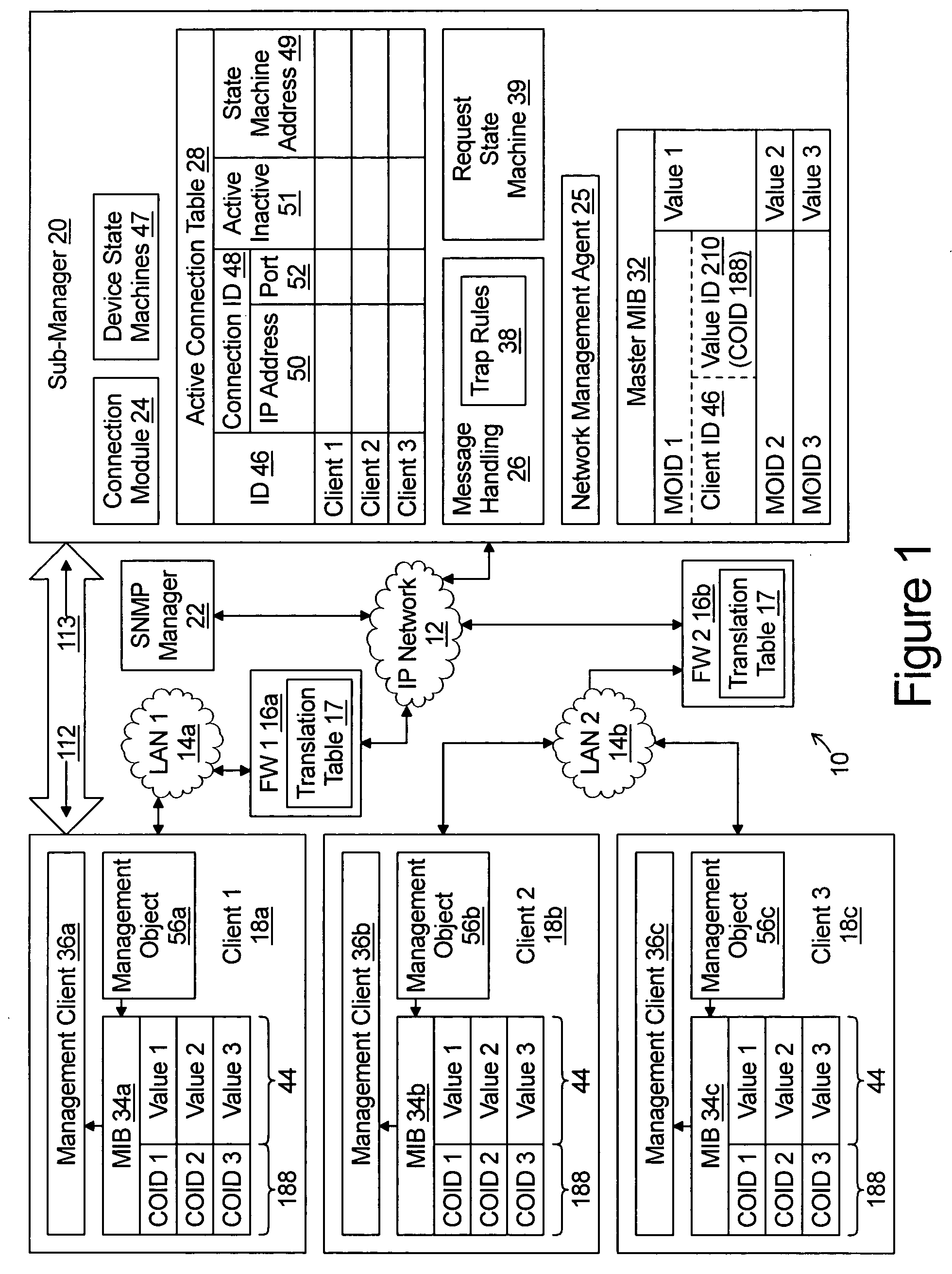
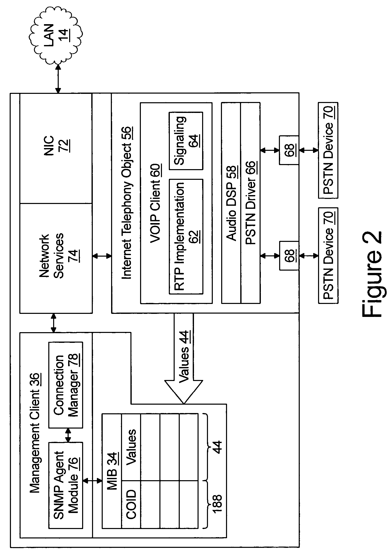
[0035] The present invention will now be described in detail with reference to the drawings. In the drawings, each element with a reference number is similar to other elements with the same reference number independent of any letter designation following the reference number. In the text, a reference number with a specific letter designation following the reference number refers to the specific element with the number and letter designation and a reference number without a specific letter designation refers to all elements with the same reference number independent of any letter designation following the reference number in the drawings.

[0036] It should also be appreciated that many of the elements discussed in this specification may be implemented in a hardware circuit(s), a processor executing software code, or a combination of a hardware circuit(s) and a processor or control block of an integrated circuit executing machine readable code. As such, the term circuit, module, server...


PUM


Abstract

A sub-manager interfaces between a traditional SNMP network management system (NMS) a plurality of clients, each of which may be served by a network address and port translation firewall. The sub-manager operates a master management information base and receives master network management request messages from the network management server. The master network management request message includes at least one master object identifier which comprises a client identifier which identifies a particular one of the clients and a variable portion that identifies a variable value within a client management information base. The sub-manager, in response, generates one or more client network management request messages to identified clients over TCP/IP connections through the firewall. The client network management request message includes a client object identifier that identifies the variable within the client management information base.

Description

TECHNICAL FIELD [0001] The present invention relates to the management of Internet telephony equipment deployed behind firewalls and more particularly to a system for interfacing between equipment deployed behind a firewall and a simple network management protocol (SNMP) based Network Management System (NMS). BACKGROUND OF THE INVENTION [0002] Development of the Internet protocols (IP) has facilitated widespread deployment of IP compliant packet switched networks for transferring of data between devices. Further, the IP addressing scheme enables the interconnecting of these IP compliant networks forming the Internet. When a device is coupled to an IP compliant network it is assigned an IP address. If the IP address is globally unique, any remote device can address IP compliant frames to the device using such globally unique IP address. [0003] Because of the limited number of IP addresses available, certain blocks of IP addresses, referred to as private network addresses, have been s...

Claims


Application Information

Patent Timeline
IPC IPC(8): H04L12/24H04L12/66H04L29/06H04L29/12
CPCH04L29/06027H04L29/12009H04L29/1233H04L41/0213H04L69/16H04L41/0803H04L43/10H04L61/25H04L41/044H04L61/00H04L65/1101
Inventor SAHA, PARTHA
Owner INNOMEDIA PTE
Why Eureka
Try Eureka