
Bulk CAS bit change detection

Inactive Publication Date: 2005-05-19
NORTEL NETWORKS LTD
View PDF4 Cites 3 Cited by
  • Summary
  • Abstract
  • Description
  • Claims
  • Application Information

AI Technical Summary

Benefits of technology

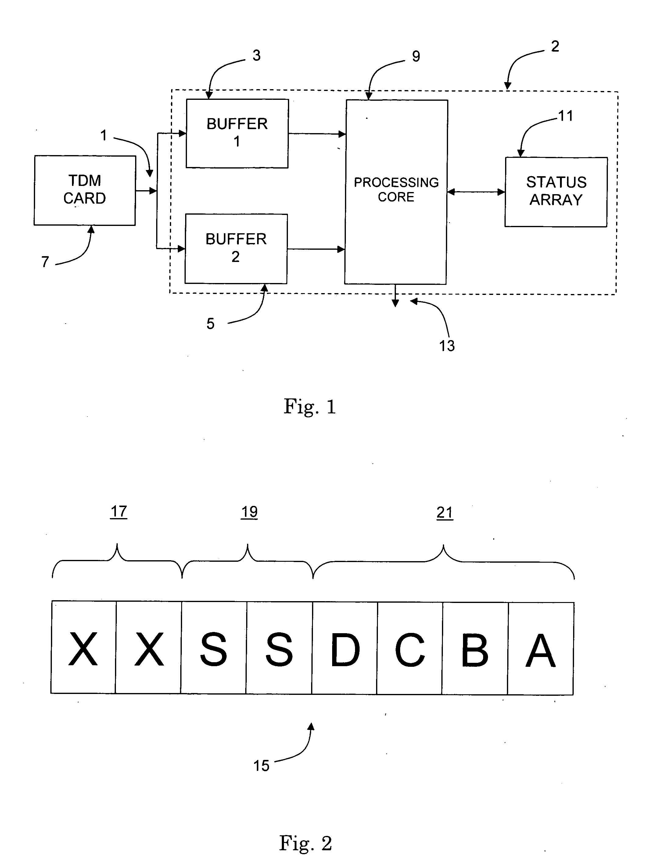
[0017] By comparing the blocks of CAS data on a row-by-row basis, the requirement for a status array is eliminated. This is because, once a row of a block of data has been written to an area of the circular memory buffer, comparison with the corresponding row in the previous block of data may begin immediately. The comparison can therefore be completed before the corresponding row in the next block of data is written to the circular memory buffer. Furthermore, the average time for changes in a timeslot of data to be detected is reduced because the comparison can begin before an entire block of data has been written to the memory.
[0019] Because only one row of CAS data is compared at a time, the comparison task is split into a large number of smaller tasks scheduled at regular intervals. This allows other tasks to be scheduled between the row comparisons, thus preventing other tasks from being blocked.
[0020] In step (ii), comparing the row with the corresponding row in the previous block preferably comprises: locating the corresponding row in the previous block by applying a fixed memory offset from the location of the row; reading the corresponding row in the previous block; and comparing the CAS data bits in each timeslot of the row with the CAS data bits in each timeslot of the corresponding row of the previous block. By applying a fixed memory offset, the processing core of a DSP can quickly locate and read the corresponding row of data from the previous block with a low processing overhead.
[0021] Data is preferably written to the circular memory buffer by direct memory access (DMA). In this way, DSP processing overhead may be minimised.
[0022] Preferably, in step (ii), after writing each row of the block of data, an interrupt is generated, and changes in the data contained in the row are determined in response to the interrupt. The use of an interrupt provides an efficient trigger for the executing the task of determining changes in the row of data.
[0024] All blocks of data are preferably written to one of two areas of the circular memory buffer. In this way, blocks are overwritten with newly received blocks. This arrangement minimises memory requirements. The size of each area of the circular memory buffer is preferably equal to the size of a block of data. The locations of the two areas of the circular memory are preferably consecutive. This also minimises memory requirements and limits the size of the fixed memory offset to the size of a block of data.

Problems solved by technology

The conventional method of detecting changes in incoming CAS data suffers a number of drawbacks that affect its reliability and efficiency.
Firstly, the comparison of an entire block of CAS data is a relatively time consuming task for the processing core of the DSP.
This is partly because access by the processing core to a status array can be slow.
If the comparison of a block of CAS data is not completed within 4 ms, a new block will overwrite the data causing errors to occur.
Secondly, because the comparison is a time consuming task, it is difficult to schedule it so that the processing core is not blocked from performing other tasks.
Thus, from receipt, the method takes significantly longer to determine changes in the first timeslots of the block of data than the last timeslots.

Method used


Image

  • Bulk CAS bit change detection
  • Bulk CAS bit change detection
  • Bulk CAS bit change detection

Examples


Embodiment Construction

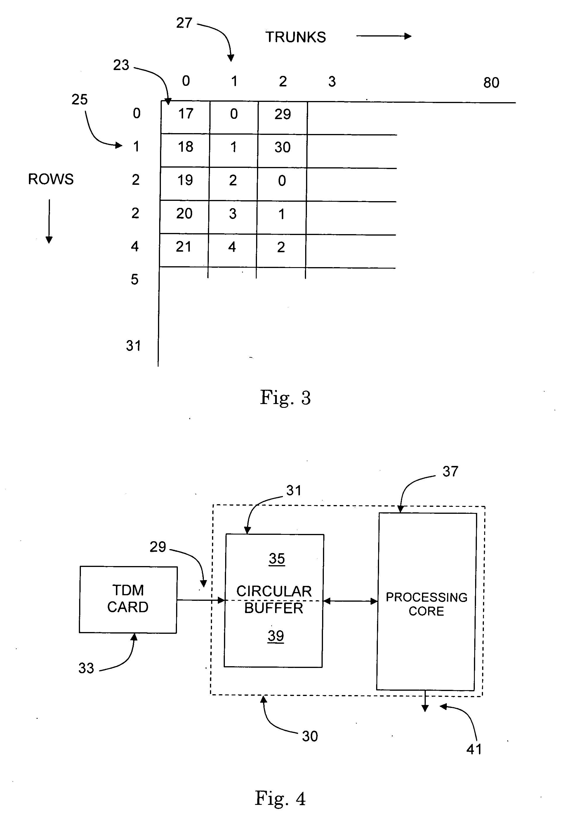
[0036]FIG. 2 shows a typical structure for a timeslot of CAS data. The timeslot of CAS data 15 is one byte long and contains the CAS data for a single communication channel.

[0037] The first two bits of data in the timeslot are framing bits 17. The framing bits 17 delineate one timeslot of CAS data form the adjacent timeslots of CAS data. The next two bits of data in the timeslot are synchronisation bits 19. The synchronisation bits 19 identify the timeslot of CAS data for the first communication channel in a trunk. The timeslots for all other communication channels in the trunk can then be identified by reference to this timeslot of CAS data. The final four bits of data in the time slot are the CAS data bits 21. The CAS data bits 21 contain information on line state changes, dialled digits and metering information for the communication channel to which the timeslot applies.

[0038]FIG. 3 shows a schematic representation of a typical format of CAS data for all of the communication ch...


PUM


Abstract

A method of detecting changes in a continuous stream of channel associated signalling (CAS) data for a plurality of communication channels is described. The method comprises the steps of: writing a block of data to an area of a circular memory buffer as a plurality of rows; writing a next block of data to an area of the circular memory buffer located sequentially after the area occupied by the previous block of data as a plurality of rows, wherein after writing each row of said next block of data, changes in the data contained in the row are determined by comparing the row with the corresponding row in the previous block of data; and repeating step (ii) a plurality of times.

Description

FIELD OF THE INVENTION [0001] The present invention relates to channel associated signalling (CAS). In particular, the present invention relates to the bulk detection of changes in CAS data bits. BACKGROUND OF THE INVENTION [0002] In communications networks, signalling equipment and signalling channels are required for the exchange of signalling information between network nodes. This signalling information informs the network nodes of line state changes, dialled digits and metering information of communication channels, for example voice channels. [0003] Signalling information may be exchanged either by channel associated signalling (CAS) or common channel signalling (CCS). A characteristic feature of CAS is that signalling information is transported along the same route as the payload data. In contrast, a characteristic feature of CCS is that signalling information is transported via a dedicated network. Although most new communication networks employ CCS, a large proportion of ex...

Claims


Application Information

Patent Timeline
IPC IPC(8): H04J3/12H04Q3/00
CPCH04Q3/0025
Inventor DOWNING, ANTHONYANSELL, JOHN
Owner NORTEL NETWORKS LTD
Learn More