
Facility Control System and Facility Control Method

a technology of facility control and control system, which is applied in the field of facility control system, can solve the problems of lowering the operation efficiency of the entire distribution facility, failure to perform failover from the operational computer, and lowering the processing efficiency of the entire facility control system, so as to increase the cost of the facility

Active Publication Date: 2013-09-26
DAIFUKU CO LTD
View PDF22 Cites 0 Cited by
  • Summary
  • Abstract
  • Description
  • Claims
  • Application Information

AI Technical Summary

Benefits of technology

The patent text describes a facility control system that can prevent the lowering of processing efficiency and increase in costs when an abnormal condition occurs in the computer that issues a task command. This is achieved by allowing the first-layer computer to execute the second-layer program after user confirmation of an abnormal condition. Additionally, this allows the first-layer computer to substitute for the second-layer computer in case of an abnormal condition, reducing the need for an additional computer. Overall, this system provides efficient and cost-effective facility control.

Problems solved by technology

However, while the inventory data can be recovered easily with such a configuration after an abnormal condition occurs in the second-layer computer, no facility controller would be available until the recovery work is completed; thus, for example, it is necessary to manually issue task commands to the first-layer computers and thus lowering of the operation efficiency of the entire distribution facility cannot be avoided.
And when an abnormal condition occurs in an operational computer, a failover is performed from the operational computer to the standby computer, in which the standby computer takes over the process performed by the program that had been executed by the operational computer in which the abnormal condition occurred.
However, in a high availability cluster, because, among other reasons, the mutually monitoring mechanism may misinterpret a momentary disruption of the network communication between the operational computer and the standby computer as an abnormal condition occurring in the operational computer, there is a possibility that a condition (so-called split-brain syndrome) may occur in which the standby computer is automatically activated by the system despite the fact that the operational computer is functioning normally.
When a plurality of task commands are issued to the first-layer computer in this manner, the same transport request may be issued again despite the fact that the transport operation of an article has been completed, which may lead to a lowering of the processing efficiency of the entire facility control system.
In addition, in a high availability cluster, it is necessary to provide, for a given operational computer, a standby computer whose sole purpose is to substitute for the operational computer, which lead to an increase in the overall cost for the facility.

Method used

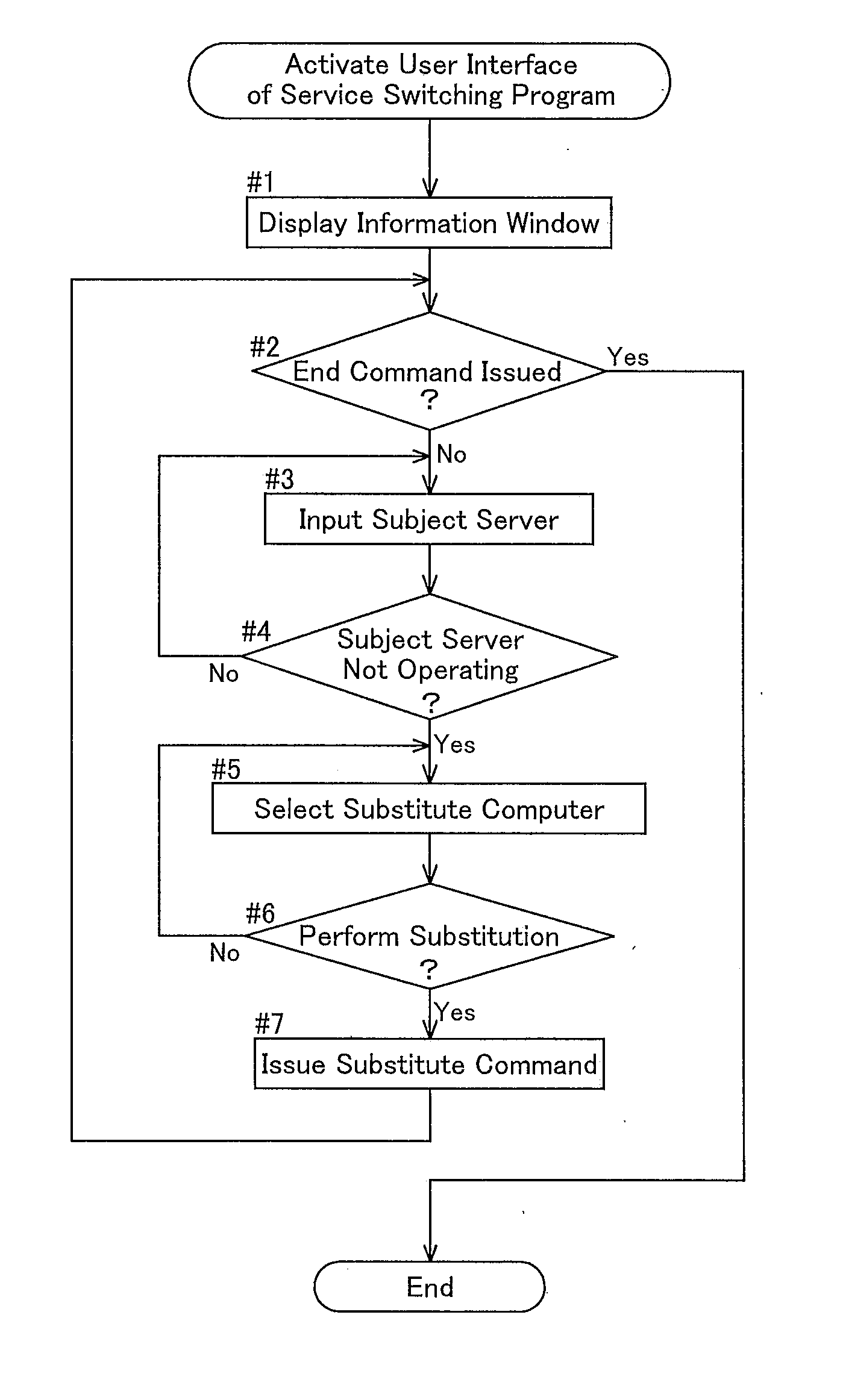
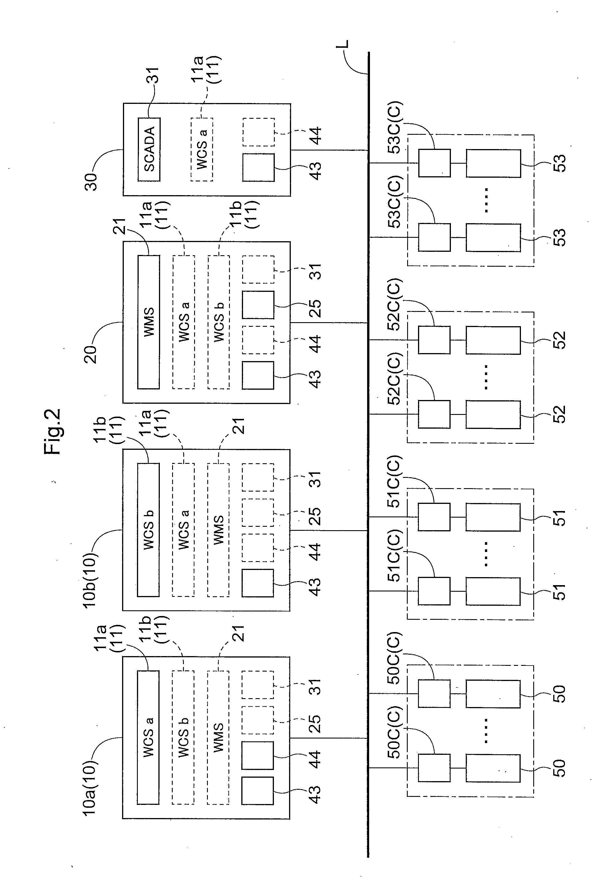

Image

  • Facility Control System and Facility Control Method
  • Facility Control System and Facility Control Method
  • Facility Control System and Facility Control Method

Examples


Embodiment Construction

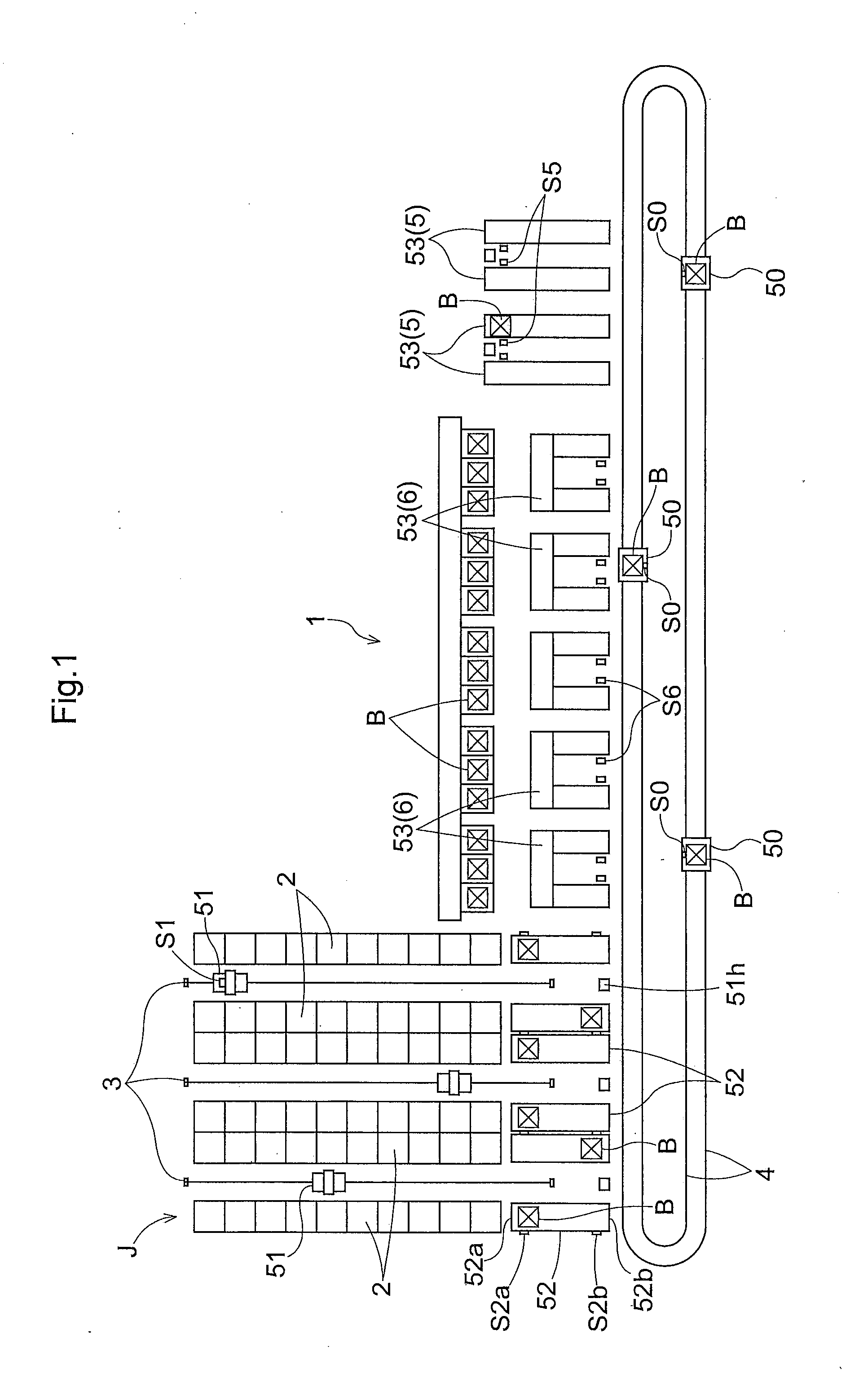
[0041]A facility control system in accordance with the present invention is described next where the control system is applied to a distribution facility 1, with reference to the drawings.

[0042]As shown in FIG. 1, this distribution facility 1 includes an automated warehouse J which primarily includes article storage racks 2 and stacker cranes 51, storing-and-retrieving conveyers 52 each of which transfers an article B to or from the stacker crane 51 provided to the automated warehouse J, receiving-and-delivering conveyors 53 which function as receiving portions for receiving articles B from outside the facility or as delivering portions for delivering articles B to outside the facility, and sorting carriages 50 which can travel along the travel rail 4 and which support and transport articles between the storing-and-retrieving conveyers 52 and the receiving-and-delivering conveyors 53.

[0043]Each article storage rack 2 has a plurality of article storage units that are arranged in the ...


PUM


Abstract

A facility control system comprises a selection processing portion that selects, based on a manual operation and when an abnormal condition occurs in a second-layer computer that issues a task command to a first-layer program which issues an apparatus operating command to an apparatus controller, whether to cause a first-layer computer to execute a second-layer program that had been executed by the second-layer computer, and a substitute command output processing portion which outputs a substitute command in accordance with selection information selected by the selection processing portion. The first-layer computer executes the second-layer program that had been executed by the second-layer computer in which the abnormal condition occurred based on a substitute command outputted by the substitute command output processing portion.

Description

BACKGROUND OF THE INVENTION[0001]1. Field of the Invention[0002]The present invention relates to a facility control system comprising an apparatus controller that controls an operation of a facility apparatus, a first-layer computer that executes a first-layer program for issuing an apparatus operating command for the facility apparatus to the apparatus controller that the first-layer computer is assigned to and for managing an operation result of the facility apparatus transmitted from the apparatus controller, a second-layer computer that executes a second-layer program for issuing a task command to the first-layer computer in order to cause the facility apparatus required to process a task request to be operated in accordance with the task request which is a request for an operation that is to be accomplished by operating the facility apparatus, and for managing a result of a task that is related to the task request based on the operation result of the facility apparatus transmit...

Claims


Application Information

Patent Timeline
Patent Type & Authority Applications(United States)
IPC IPC(8): G05B9/02
CPCG05B9/02G06F11/202G06F11/2023G06F11/2033G06F11/2035
Inventor IKAWA, KOUICHIMORI, KAZUTO
Owner DAIFUKU CO LTD
Learn More