
Steam turbine facility

a steam turbine and facility technology, applied in the direction of machines/engines, stators, liquid fuel engines, etc., can solve the problems of difficult manufacturing of difficult implementation of the facility illustrated in fig. 4, and inability to manufacture large-sized turbine rotors or casings, etc., to reduce the amount of materials used, reduce the manufacturing cost of the entire facility, and reduce the amount of material used

Active Publication Date: 2010-08-12
MITSUBISHI POWER LTD
View PDF6 Cites 2 Cited by
  • Summary
  • Abstract
  • Description
  • Claims
  • Application Information

AI Technical Summary

Benefits of technology

[0012]Accordingly, the invention was made in view of the problems of the conventional technique, and the object thereof is to provide a steam turbine facility capable of suppressing the possibility of vibration occurrence and a drastic increase in facility costs, thereby realizing an increase in size of the facility, even if a steam condition of 650° C. or higher is adopted.

Problems solved by technology

In the technique disclosed in Patent Document 1, however, when a steam turbine facility with large capacity is considered, the facility illustrated in FIG. 4 is difficult to implement.
When such a material as Ni-based alloy capable of withstanding steam with a temperature of 650° C. or higher is used to form the first intermediate-pressure turbine 112, it is difficult to manufacture a turbine rotor or casing weighing 10t or more in terms of the limitation of material manufacturing, and it is impossible to manufacture a large-sized turbine rotor or casing.
In this case, however, the number of casings increases, and thus the number of buildings or pipes increases.
Therefore, the manufacturing costs of the facility inevitably increases.
Additionally, as the number of shafts (divided turbines) increases, it is highly likely that vibrations occur.
In this case, however, a large amount of cooling steam needs to be introduced into the casings.

Method used


Image

  • Steam turbine facility
  • Steam turbine facility
  • Steam turbine facility

Examples


example 1

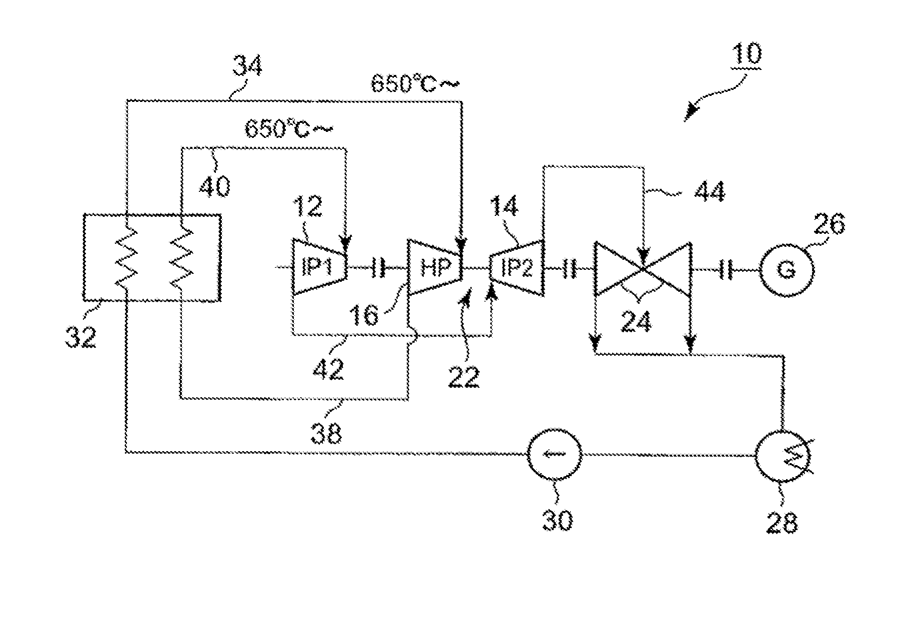
[0029]FIG. 1 is a view illustrating the configuration of a steam turbine power generation facility according to Example 1 of the invention.

[0030]As illustrated in FIG. 1, the steam turbine power generation facility according to Example 1 of the invention will be described.

[0031]The steam turbine power generation facility 10 illustrated in FIG. 1 includes a high-pressure turbine 16, an intermediate-pressure turbine separated into two as will be described later, a low-pressure turbine 24, a generator 26, a condenser 28, and a boiler 32 as main components. The intermediate-pressure turbine is separated into a first intermediate-pressure turbine 12 on a high-temperature and high-pressure side and a second intermediate-pressure turbine 14 on a low-temperature and low-pressure side, and the high-pressure turbine 16 and the second intermediate-pressure turbine 14 are integrated to form an integrated structure 22.

[0032]Additionally, the first intermediate-pressure turbine 12, the integrated...

example 2

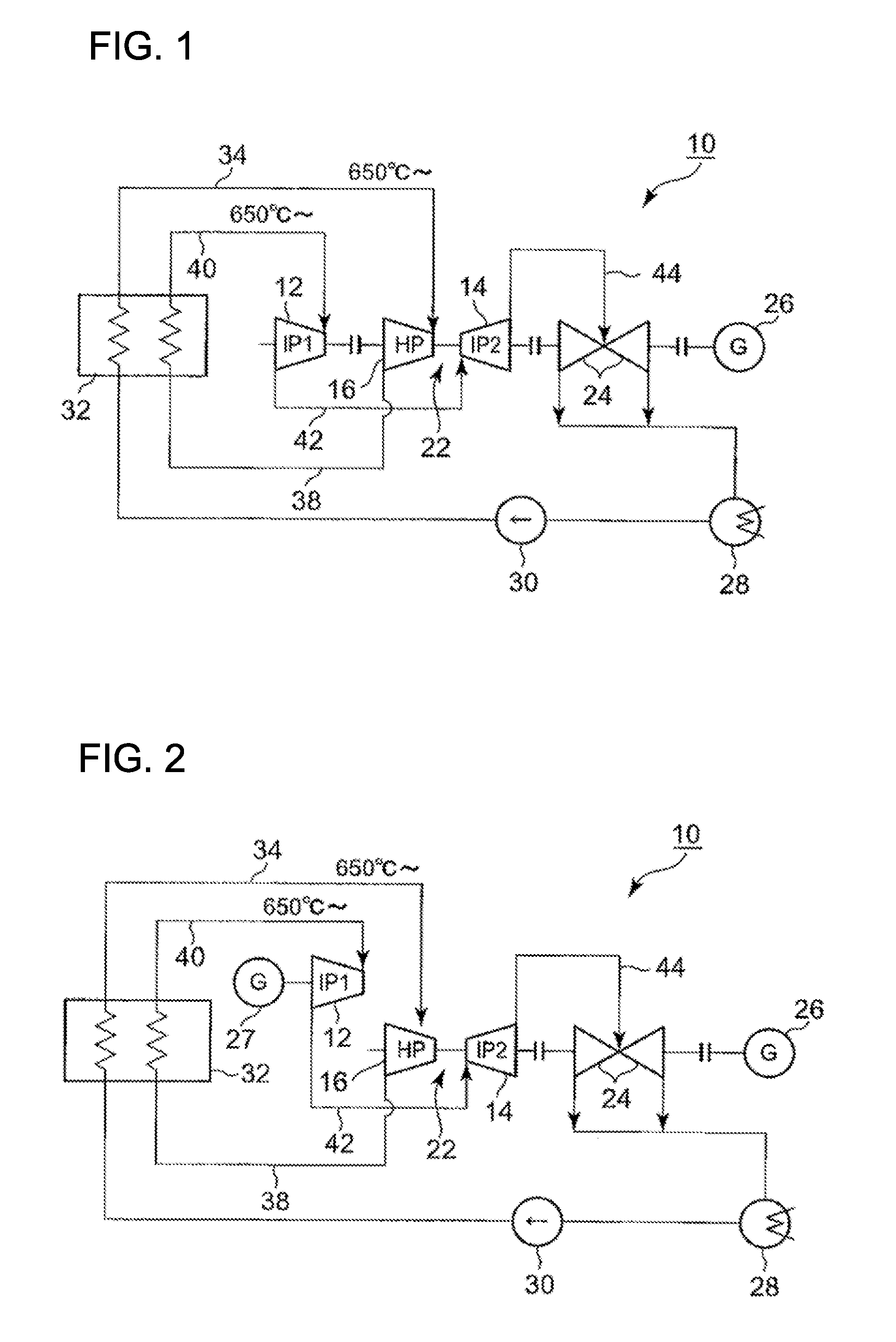
[0037]FIG. 2 is a view illustrating the configuration of a steam turbine power generation facility according to Example 2 of the invention.

[0038]As illustrated in FIG. 2, the steam turbine power generation facility according to Example 2 of the invention will be described.

[0039]The steam turbine power generation facility 10 illustrated in FIG. 2 includes a high-pressure turbine 16, an intermediate-pressure turbine separated into two as will be describer later, a low-pressure turbine 24, generators 26 and 27, a condenser 28, and a boiler 32 as main components. The intermediate-pressure turbine is separated into a first intermediate-pressure turbine 12 on a high-temperature and high-pressure side and a second intermediate-pressure turbine 14 on a low-temperature and low-pressure side, and the high-pressure turbine 16 and the second intermediate-pressure turbine 14 are integrated to form an integrated structure 22.

[0040]Additionally, the integrated structure 22, the low-pressure turbin...

example 3

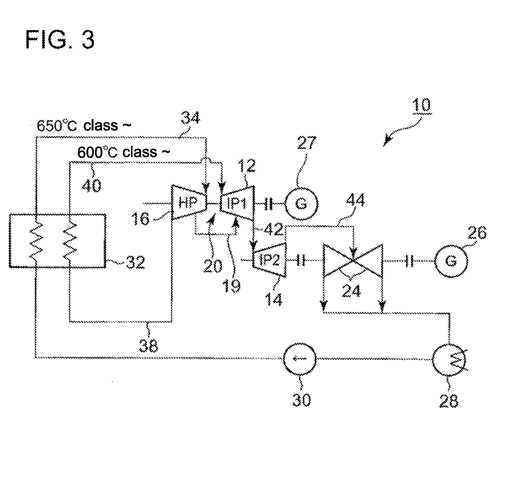
[0046]FIG. 3 is a view illustrating the configuration of a steam turbine power generation facility according to Example 3 of the invention.

[0047]The steam turbine power generation facility 10 illustrated in FIG. 3 is constructed by partially changing the configuration of the steam turbine power generation facility according to Example 2 of the invention, which is illustrated in FIG. 2. The following descriptions will be focused on different components from those of Example 2 of the invention.

[0048]In the steam turbine power generation facility 10 illustrated in FIG. 3, the high-pressure turbine 16 and the first intermediate-pressure turbine 12 are integrated to form an integrated structure 20. The second intermediate-pressure turbine 14, the low-pressure turbine 24 and the generator 26 are connected together on the same axis so as to form a connection structure, and the integrated structure 20 and the generator 27 are connected together on the same axis so as to be arranged at a pos...


PUM

PropertyMeasurementUnit
temperatureaaaaaaaaaa

Abstract

Provided is a steam turbine facility capable of suppressing the possibility of vibration occurrence and a drastic increase in facility cost, thereby realizing an increase in size of the facility, even if steam conditions of 650° C. or higher are adopted. In a steam turbine facility including a high-pressure turbine, an intermediate-pressure turbine, and a low-pressure turbine, the intermediate-pressure turbine is separated into a first intermediate-pressure turbine on a high-temperature and high-pressure side and a second intermediate-pressure turbine on a low-temperature and low-temperature side, at least any one of the rotors and casings of the steam-introduction-side turbines into which steam with a temperature of 650° C. or higher is introduced is formed from Ni-based alloy, and at least any one of the overall rotors and the overall casings of the turbines are constructed by joining together a plurality of rotor members or casing members by welding.

Description

TECHNICAL FIELD[0001]The present invention relates to a steam turbine facility including a high-pressure turbine, an intermediate-pressure turbine, and a low-pressure turbine.BACKGROUND ART[0002]The three methods of atomic power, thermal power, and hydraulic power generation, are now used as main power generation methods, and from a viewpoint of resource quantity and energy density, the three power generation methods are also expected to be used as main power generation methods in the future. Especially, since thermal power generation is safe, and its utility value is high as a power generation method with a high capacity to respond to load changes, it is expected that the thermal power generation will also continue to play an important role in the power generation field in the future.[0003]In general, a steam turbine facility, which is used in a coal-fired power station including steam turbines, is provided with a high-pressure turbine, an intermediate-pressure turbine, and a low-p...

Claims


Application Information

Patent Timeline
Patent Type & Authority Applications(United States)
IPC IPC(8): F01D5/28F01D25/24
CPCF01D5/063F05D2220/31F05C2201/0466F01K7/18F01D25/24F05D2300/175
Inventor NISHIMOTO, SHINTANAKA, YOSHINORIFUJIKAWA, TATSUAKIYAMAMOTO, RYUICHI
Owner MITSUBISHI POWER LTD
Learn More