Method and circuit for timing pulse generation

Inactive Publication Date: 2005-05-19
FUJITSU LTD
View PDF3 Cites 6 Cited by
  • Summary
  • Abstract
  • Description
  • Claims
  • Application Information

AI Technical Summary

Benefits of technology

[0037] It is accordingly an object of the present invention to provide a method and a circuit for timing pulse generation which can provide a switchover without instantaneous interruption upon a stable and manual switchover, without an occurrence of errors even when a monitoring window is erroneously prepared or generated by a frame pulse generated in an unstable state, and a reference timing pulse position changes every switchover.

Problems solved by technology

As described above, there have been disadvantageous in the read timing pulse generation circuit used for the main signal data switching circuit and the master timing pulse generation circuit for generating the master timing pulse which forms a base of the frame pulse used for the main signal data switching circuit, as follows:

Method used


Image

  • Method and circuit for timing pulse generation
  • Method and circuit for timing pulse generation
  • Method and circuit for timing pulse generation

Examples


Embodiment Construction

[1] Embodiment of Read Timing Pulse Generation Circuit

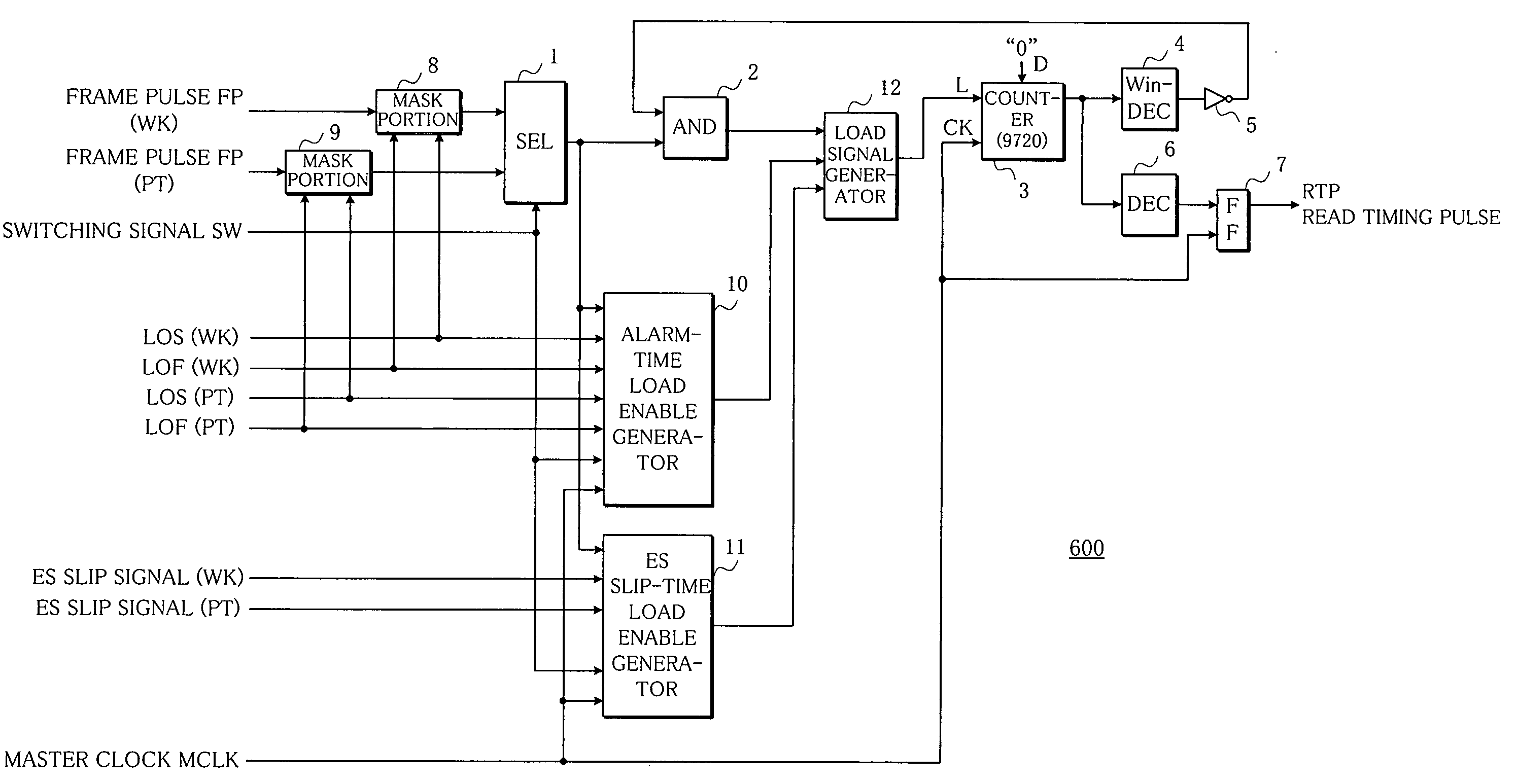
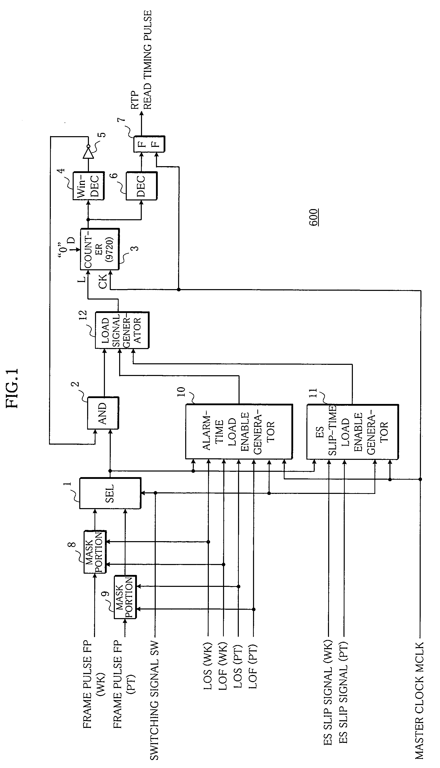
[0074]FIG. 1 shows an embodiment of a read timing pulse generation circuit as a timing pulse generation circuit realizing a timing pulse generation method according to the present invention. This embodiment is different from the prior art example shown in FIG. 8 in that mask portions 8 and 9 of a working system and a protection system are respectively provided in front of the selector 1, and an alarm-time load enable generator 10 for generating a monitoring window at an optimum time, an ES slip-time load enable generator 11, and a load signal generator 12 for receiving output signals of the generators 10 and 11 and for providing a monitoring window generation request signal, i.e. a load request signal to a counter 3 are provided for the monitoring window generation circuit composed of the AND gate 2, the counter 3, the monitoring window generator 4, and the inverter 5.

[0075] Hereinafter, each portion of the embodiment will now ...


PUM


Abstract

In a method and a circuit for timing pulse generation, a frame pulse of a corresponding system is masked when an alarm signal of either a working system or a protection system is received, a monitoring window which indicates an absorbable range of delay time difference between the frame pulses is generated upon an arrival of the frame pulse of the system selected by a switching signal, when the alarm signal of a system not selected is generated upon selection of the switching signal. Alternatively, a request signal for regenerating the monitoring window which indicates an absorbable range of delay time difference between the frame pulses is provided upon an arrival of the frame pulse of the system selected by the switching signal, when a slip signal is generated upon selection of the switching signal. The monitoring window is generated around the frame pulse selected by the switching signal when the monitoring window generation request signal is received, a read timing pulse common to memories of both systems is generated at a predetermined timing position, and the monitoring window is regenerated when the selected frame pulse deviates from the monitoring window. Alternatively, a correction signal including a number and a direction of bits when a reference timing pulse not selected deviates from the monitoring window is generated to be transmitted, the correction signal is extracted from a main signal received, and a position of the reference timing pulse of the protection system is corrected based on the correction signal, when the protection system is presently selected.

Description

BACKGROUND OF THE INVENTION [0001] 1. Field of the Invention [0002] The present invention relates to a method and a circuit for timing pulse generation, and in particular to a method and a circuit for hitless timing pulse generation which manually switch frame pulses or reference timing pulses of a working system and a protection system and to prevent errors from arising upon generation of read timing pulses or master timing pulses respectively. [0003] 2. Description of the Related Art [0004] In recent communication devices, a high quality of transmitting signals is required, and signals with large capacity have been processed, together with a high integration of the communication devices, whereby generated timing pulses are extremely influenced by a signal switchover operation between a working system and a protection system. Therefore, a demand for generation of error-free timing pulses without any instantaneous interruption has been growing when the switchover is manually execute...

Claims


Application Information

Patent Timeline
Patent Type & Authority Applications(United States)
IPC IPC(8): H04J3/06G06F1/10H03K5/1252H03K7/04H04L7/00
CPCH03K5/1252G06F1/10
Inventor MOCHIZUKI, HIDEAKI
Owner FUJITSU LTD
Why Eureka
Try Eureka