Systems and methods for estimating helium production in shrouds of nuclear reactors

Inactive Publication Date: 2005-05-19
GENERAL ELECTRIC CO
View PDF8 Cites 13 Cited by
  • Summary
  • Abstract
  • Description
  • Claims
  • Application Information

AI Technical Summary

Problems solved by technology

Internal structures of operating BWRs are suscept

Method used


Image

  • Systems and methods for estimating helium production in shrouds of nuclear reactors
  • Systems and methods for estimating helium production in shrouds of nuclear reactors
  • Systems and methods for estimating helium production in shrouds of nuclear reactors

Examples


Embodiment Construction

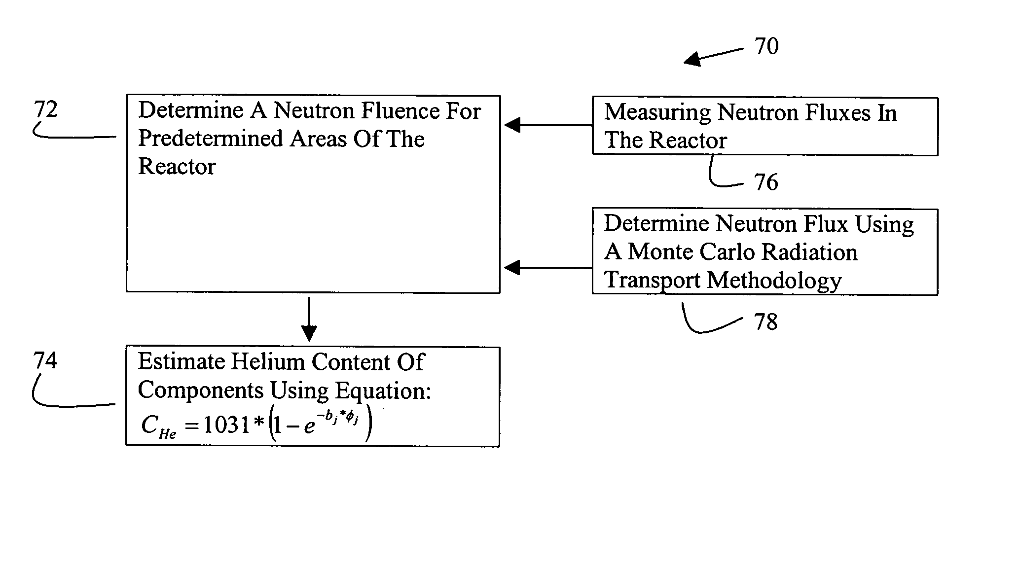
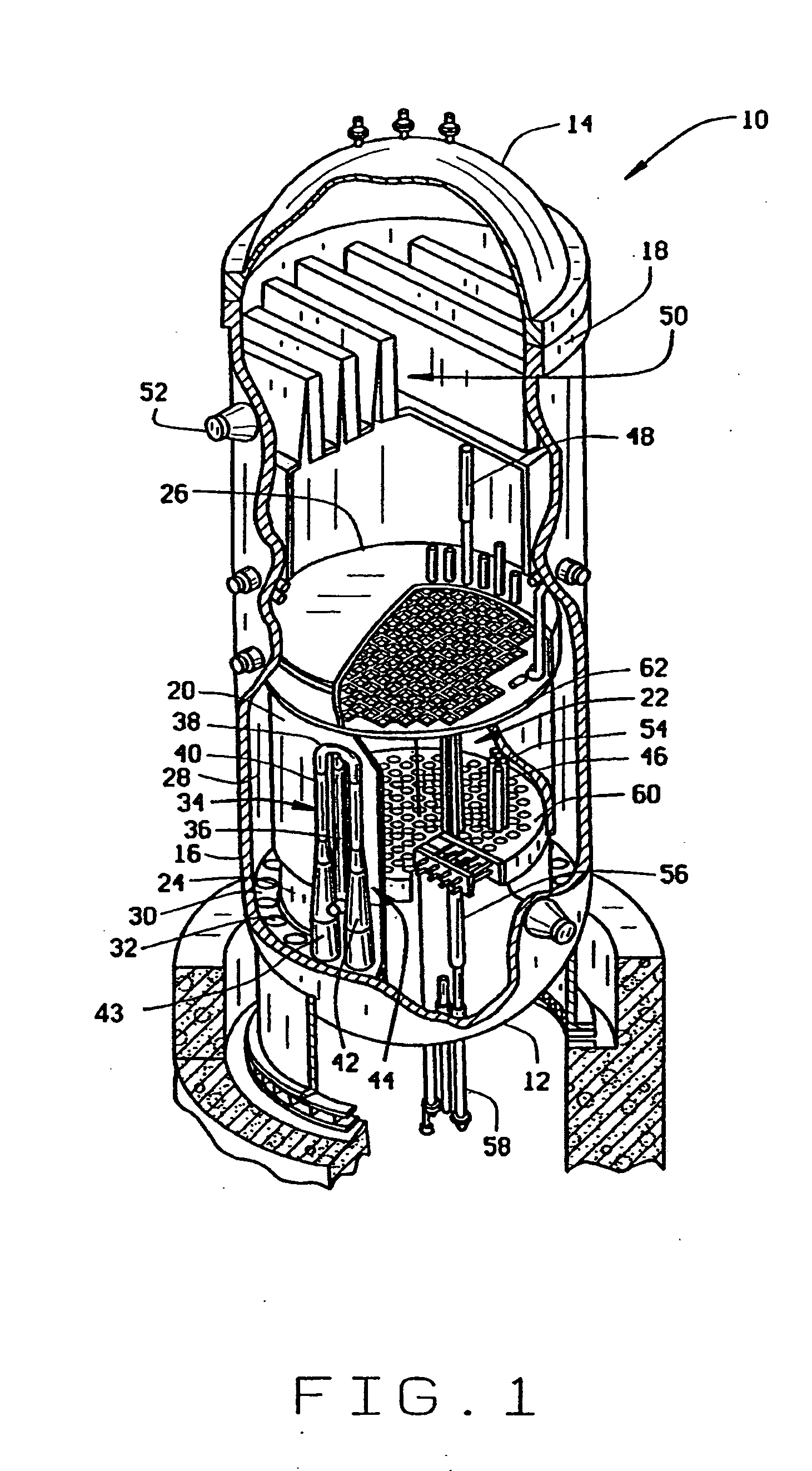
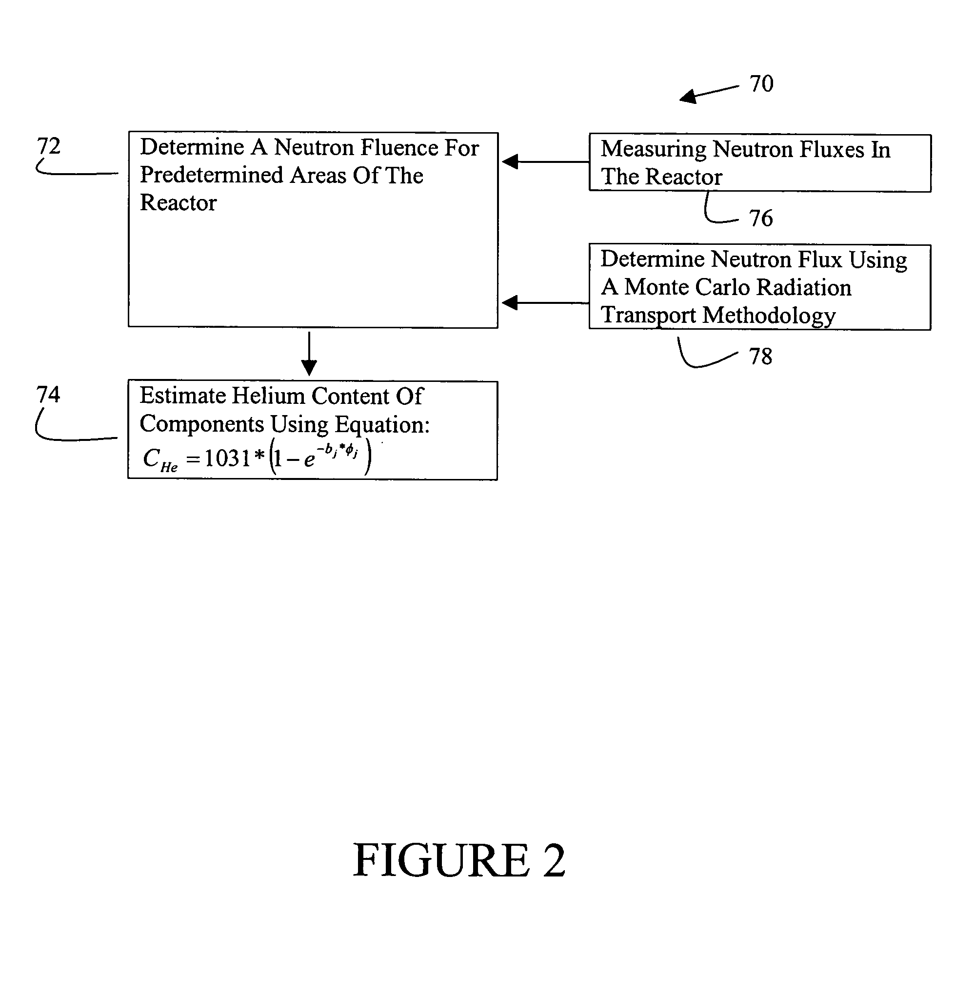
[0016] A method for estimating a helium content of a stainless steel shroud in a boiling water nuclear reactor is described below in detail. The method includes determining the neutron fluence at predetermined locations in the reactor, for example, at the shroud. Neutron fluences are determined by measuring neutron fluxes in a reactor or by using computational simulator systems.

[0017] In one embodiment, neutron fluence computational systems include a Monte Carlo computer program, a fuel simulator, a core simulator, and pre-, inter-, and post-processors among the Monte Carlo, fuel and core simulators, and are described below in detail. Interpolating various fuel exposure- and void-dependent nuclide data tracked by core and fuel simulators generates material composition input for the Monte Carlo program. The Monte Carlo computer program is run in a criticality mode in one exemplary embodiment, or in a combination of criticality mode and fixed source mode in another embodiment, to com...


PUM


Abstract

A method for estimating a helium content of the stainless steel core shroud in a boiling water nuclear reactor includes, in an exemplary embodiment, determining a neutron fluence for predetermined areas of the reactor, and estimating a helium content of the stainless steel shroud at predetermined areas of the reactor using the following equation: CHe=1031*(1−e−b<sub2>j</sub2><sub2>j</sub2>), where CHe is the helium concentration as atomic parts per billion of helium in the stainless steel shroud per weight parts per million of boron in the stainless steel shroud, bj is a value between about 2.50 e−21 and about 5.00 e−21, φj is fluence expressed as neutrons per square centimeter, and subscript j denotes thermal fluence or fast fluence.

Description

CROSS REFERENCE TO RELATED APPLICATIONS [0001] This application is a continuation-in-part of U.S. patent application Ser. No. 10 / 210,214 filed Jul. 31, 2002.BACKGROUND OF THE INVENTION [0002] This invention relates generally to nuclear reactors and more particularly, to systems and methods for estimating helium production in the stainless steel shroud in a boiling water nuclear reactor. [0003] A reactor pressure vessel (RPV) of a boiling water reactor (BWR) typically has a generally cylindrical shape and is closed at both ends, e.g., by a bottom head and a removable top head. A core assembly is contained within the RPV and includes the core support plate, fuel bundles, control rod blades and a top guide. A core shroud typically surrounds the core assembly and is supported by a shroud support structure. Particularly, the shroud has a generally cylindrical shape and surrounds both the core plate and the top guide. There is a space or annulus located between the cylindrical reactor pre...

Claims


Application Information

Patent Timeline
IPC IPC(8): G01N33/20G21C17/003G21CG21C1/08G21C17/00G21C17/01G21C19/00G21D1/00
CPCG21C17/00G21C17/003G21C17/01Y02E30/40G21Y2002/104G21Y2002/303G21Y2004/40G21D3/001Y02E30/30Y02E30/00
Inventor SITARAMAN, SHIVAKUMARCHIANG, REN-TAIJENKINS, ALTON LEWIS
Owner GENERAL ELECTRIC CO
Why Eureka
Try Eureka