Coupling device for an artificial model

a technology of coupling device and artificial model, which is applied in the direction of rod connection, coupling, dolls, etc., can solve the problems of artificial model falling down or askew, parts that oscillate, and cannot obtain a firm joint, etc., and achieves the effects of convenient replacement of damaged parts, low wear, and little resistan

Inactive Publication Date: 2005-05-19
CHIANG JUNG CHANG
View PDF3 Cites 4 Cited by
  • Summary
  • Abstract
  • Description
  • Claims
  • Application Information

AI Technical Summary

Benefits of technology

[0014] A further object of the present invention is to provide a coupling device for an artificial model with parts thereof being fastened by way of bolts so that it is convenient for replacing damage parts quickly without the need of being fixed in shop.
[0015] A further object of the present invention is to provide a coupling device for an artificial model with two sets of elastic bodies to allow the male connecting member, the female connecting member and the pin generating a defense compressing space during rotating such that it is possible to obtain a coupling device with low wear, little resistance and low chance of damage and it is more easy to be operated and assembled.

Problems solved by technology

However, the stem device 33 is too much simply constructed so that it is not possible to obtain a firm joint between the hip part 31 and the thigh part due to a clearance 34 being generated.
Moreover, it is easy for the thigh part to oscillate and result in the artificial model falling down or askew exhibited clothes due to an unbalancing center of gravity of the artificial model.
Furthermore, once the stem device 33 is out of order, it is hard to be fixed unless the whole set of the artificial model is delivered to the repair shop and it becomes extremely inconvenient and less economical.

Method used


Image

  • Coupling device for an artificial model
  • Coupling device for an artificial model
  • Coupling device for an artificial model

Examples


Embodiment Construction

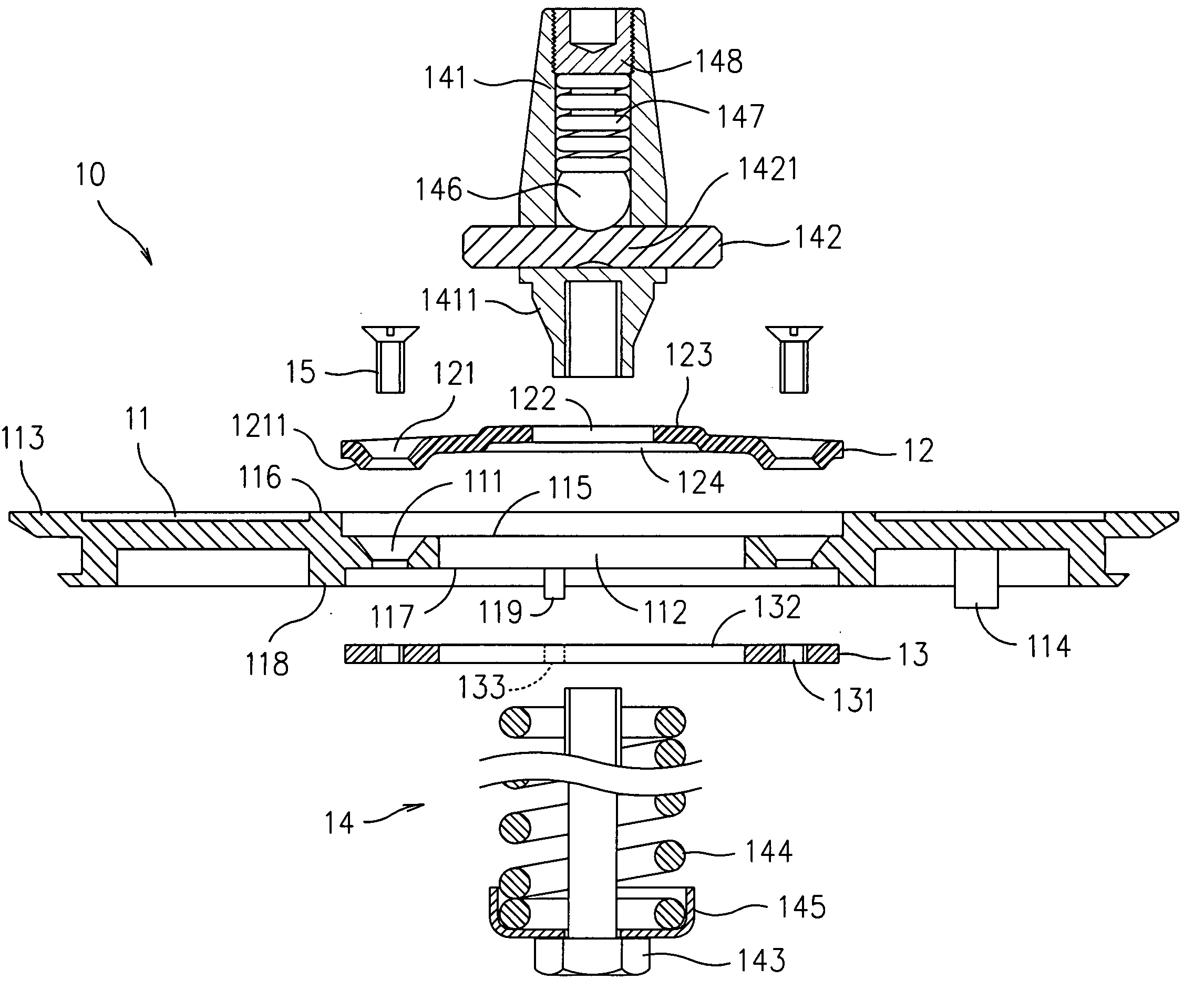
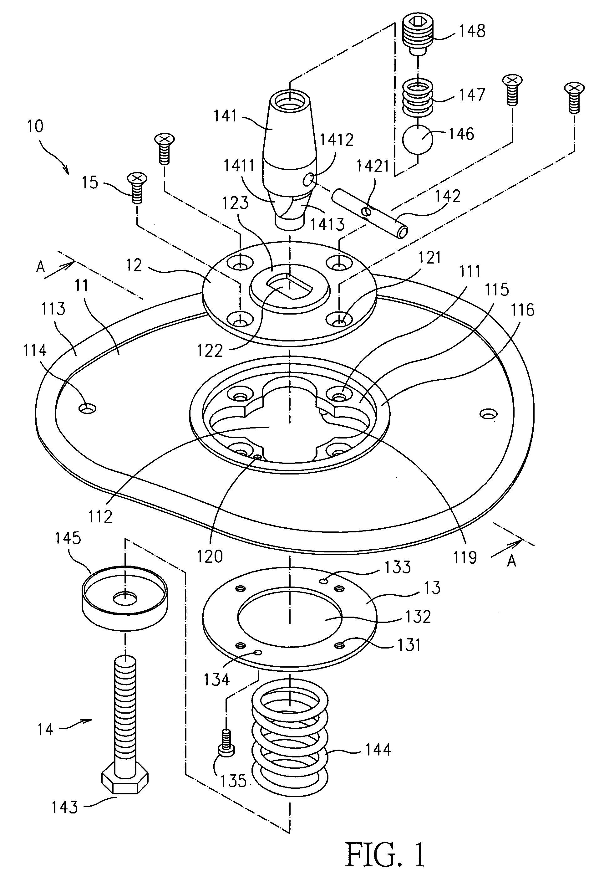
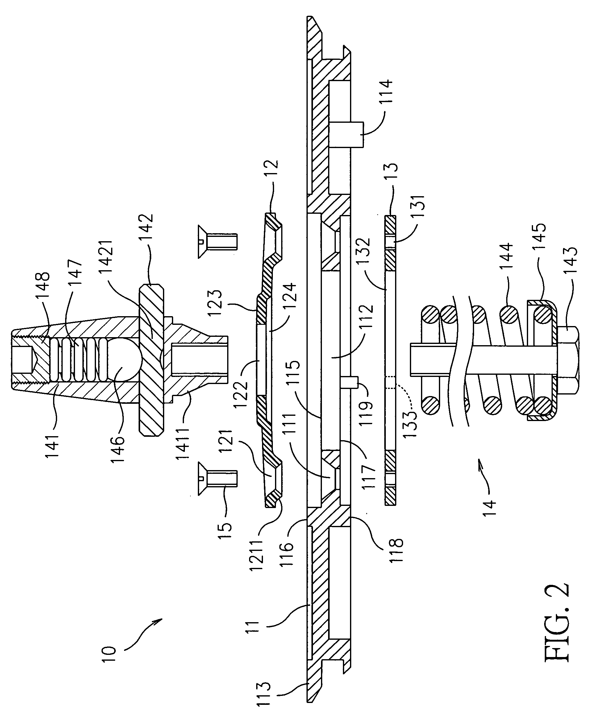
[0031] Referring to FIGS. 1 to 3, a coupling device for an artificial model according to the present invention provides a male joining part 10, which includes a base disk 11, a front positioning plate 12, a rear positioning lock plate 13 and an insertion member 14.

[0032] The base disk 11 at the periphery thereof is provided with an upright rim 113 and at the center thereof is provided with a hollow central part 112. Two opposite threaded holes 114 with respect to the hollow central part 112 and disposed near the upright rim 113 pierce the base disk 11 and the two threaded holes allow the base disk 11 to be located at one of the connection interfaces on the separated hips. The base disk 11 at two facial sides thereof has a recess 115, 117 respectively and the recesses 115, 117 at the circumferences thereof have a flange 116, 118 respectively. A partition between the recesses 115, 117 surrounds the hollow central part 113 and is provided with four threaded holes 111 with a countersin...


PUM


Abstract

A coupling device for an artificial model includes a male joining part and a female joining part, which is joined to the male joining part tightly. The male joining part has the front positioning plate thereof providing a central circular protrusion, the insertion member thereof is composed of an insert head, a pin, an adjustment bolt, an elastic body and a covering cap with the insert head having a conical shape and an elongated flat part at the bottom thereof with the pin being inserted into the insert head along a radial direction of the insert head and passing through an axis of the insert head to form a shape of cross, and a hollow center thereof has a shape corresponding to the elongated flat part of the insert head such that the elongated flat part of the insert head can fit with the hollow center after being inserted into the hollow center with the adjustment bolt passing through the cap and the elastic body before engaging with the bottom of insert head. The female joining part has the front positioning plate with a center thereof providing a hollow part with a plurality of equidistant radial grooves and two opposite ones of the radial grooves are pierced with the pin; and a radial recess is disposed between two neighboring ones of the radial grooves respectively. Hence, the male joining member and the female joining member can be joined to each other tightly and be inserted into each other for achieving a purpose of positioning.

Description

BACKGROUND OF THE INVENTION [0001] 1. Field of the Invention [0002] The present invention relates to a coupling device for an artificial model, and, particularly, to a coupling device, which has a male connecting member and a female connecting member being attached to two opposite connecting surfaces of the neck and the hip of the artificial model respectively to secure the two connecting surfaces being joined to each other tightly by way of two sets of elastic bodies engaging with each other. [0003] 2. Description of Related Art [0004] Referring to FIG. 10, the conventional artificial model 30 at the hip part 31 and the thigh part 32 thereof provides a stem device 33 at two opposite connecting surfaces respectively. In order to put on pants, it is necessary to detach the thigh part 32 from the hip part 30 in advance and the pants can be put on the thigh part 32 before the stem device 33 on the thigh part 32 can be inserted into the hip part 30. However, the stem device 33 is too mu...

Claims


Application Information

Patent Timeline
Patent Type & Authority Applications(United States)
IPC IPC(8): A47F8/00
CPCA47F8/00Y10T403/75Y10T403/76Y10T403/1616Y10T403/1624Y10T403/32057Y10T403/7005Y10T403/69Y10T403/592
Inventor CHIANG, JUNG-CHANG
Owner CHIANG JUNG CHANG
Why Eureka
Try Eureka