Systems and methods for improved engagement between aligners and teeth

a technology of aligner and teeth, applied in the field of orthodontics, can solve the problems of unsightly and uncomfortable, difficult brushing, flossing between teeth and other dental hygiene procedures, and time-consuming process, and achieve the effects of enhancing the surface detail of the virtual attachment, increasing the force transmitted by the polymeric shell, and enhancing the surface detail

Inactive Publication Date: 2005-05-19
ALIGN TECH
View PDF40 Cites 36 Cited by
  • Summary
  • Abstract
  • Description
  • Claims
  • Application Information

AI Technical Summary

Benefits of technology

[0013] In many embodiments the pre-selected distance over which the locus of engagement extends is at least about 0.5 mm. The distance may be at least about 1 mm. The force transmitting component and force receiving component may be arranged to rotate at least one of the teeth with the transmitted force. In some embodiments the force transmitting component and force receiving component are arranged to extrude at least one of the teeth with the transmitted force. Alternatively, the force transmitting component and force receiving component may be arranged to intrude at least one of the teeth with the force. The force transmitting component and the force-receiving component may comprise a cam and a follower. In some embodiments the contact point adjusts position within the locus of engagement, and this adjustment establishes and equilibrium as the force transmitted to the at least one tooth which lags its intended position is increased.
[0022] In some embodiments the model is a computer model and the attachment is virtual attachment. Modifying the virtual attachment forms a modified virtual attachment. The modified virtual attachment may be for forming the attachment receptacle in the polymeric shell. The modifying of the virtual attachment may include modifying a position of the virtual attachment. The modified virtual attachment may be similar to a shape of at least a portion of the virtual attachment, for example a similar shape formed by truncating a portion of the virtual attachment. In preferred embodiments, the modifying of the virtual attachment increases the force transmitted by the polymeric shell. The modifying of the virtual attachment may include enhancing a surface detail of the virtual attachment to form a modified virtual attachment having enhanced surface detail.

Problems solved by technology

Although conventional braces are effective, they are often a tedious and time consuming process requiring many visits to the orthodontist's office.
Moreover, from a patient's perspective, they are unsightly and uncomfortable.
Moreover, the archwire and ligatures which connect the brackets in a continuous network make brushing, flossing between the teeth and other dental hygiene procedures difficult, possibly contributing to the development of gingivitis.
For example, shell-like elastic polymeric positioning appliances have difficulty applying certain forces to individual teeth, such as extrusive force (e.g. pulling or raising a tooth relative to the jaw).
Particularly difficult tooth movements are rotations and extrusions.
However, during treatment, coupling between an appliance and attachment may become disengaged.
If the planned position of the tooth and attachment differs from the actual position of the tooth and attachment, the receptacle for the attachment formed in the polymeric shell may not properly receive the attachment on the tooth.
If the receptacle formed in the polymeric shell does not properly receive the attachment, the force applied to the tooth decreases and the treatment outcome may be less than ideal.

Method used


Image

  • Systems and methods for improved engagement between aligners and teeth
  • Systems and methods for improved engagement between aligners and teeth
  • Systems and methods for improved engagement between aligners and teeth

Examples


Embodiment Construction

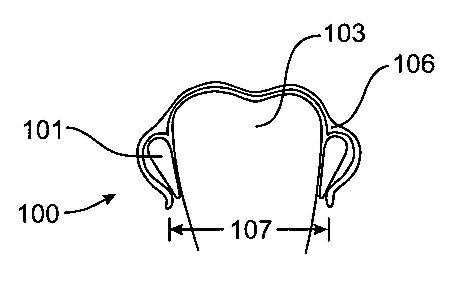
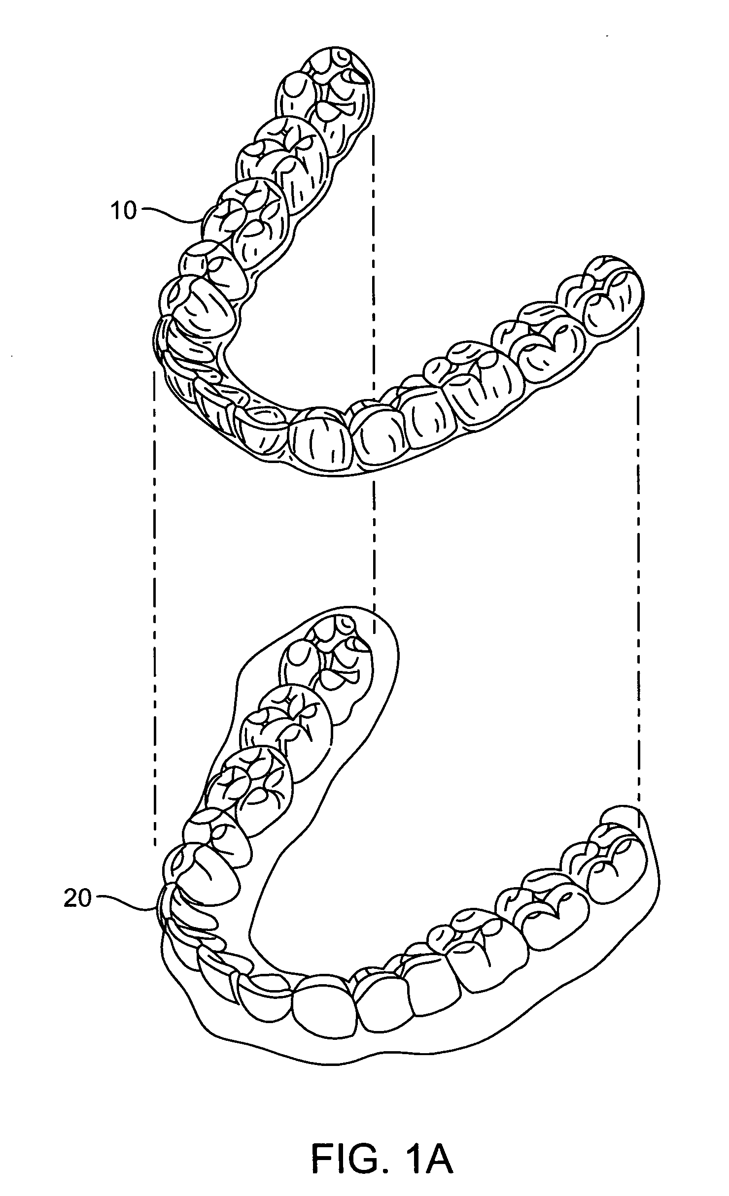
[0056] The present invention provides improved systems and methods for moving teeth by positioning appliances over teeth. Appliances are often referred to as aligners. An appliance 10 and set of teeth 20 are illustrated in FIG. 1A. Specific systems and methods for producing the appliances are described in U.S. Pat. No. 5,975,893, the full disclosure of which is incorporated herein by reference. The teeth are bonded to attachment devices to effect rotation, translation, intrusion and extrusion of the teeth. Attachment devices and appliances for incorporating the present invention are described in U.S. Pat No. 6,309,215, the full disclosure of which is incorporated herein by reference. A series of appliances are positioned over the teeth and attachments to reposition teeth from an initial position to a final position. Interactions of the attachment devices and appliances include cam and follower, meshing gear, and ratchet and pawl type interactions. The interactions of the present inv...


PUM

PropertyMeasurementUnit
distanceaaaaaaaaaa
distanceaaaaaaaaaa
lengthaaaaaaaaaa

Abstract

A system and method for repositioning teeth in a patient jaw includes an attachment bonded to a tooth. The attachment has at least one force receiving component for receiving a force. A polymeric shell repositioning appliance is positioned over at least some of the teeth in the patient jaw. The polymeric shell has at least one force transmitting component for engaging the force receiving component to form a locus of engagement. The locus of engagement transmits the force and moves but is maintained as the tooth is repositioned. In specific embodiments the locus of engagement is maintained over a substantial range of motion. The force transmitted at the locus of engagement increases in response to the tooth lagging an intended position. A space between the positioned appliance and the tooth permits the tooth to move into an intended position.

Description

CROSS-REFERENCES TO RELATED APPLICATIONS [0001] The present application is a continuation of U.S. patent application Ser. No. 10 / 126,105 (Attorney Docket No. 018563-006300 / AT-00119), filed Apr. 18, 2002, the full disclosure of which is incorporated herein by reference.BACKGROUND OF THE INVENTION [0002] The present invention is related generally to the field of orthodontics. More particularly, the present invention is related to improved systems and methods for removably attaching a dental positioning appliance to the dental features of a patient during orthodontic treatment. [0003] Orthodontic treatments involve repositioning misaligned teeth and improving bite configurations for improved cosmetic appearance and dental function. Repositioning teeth is accomplished by applying controlled forces to the teeth over an extended period of time. This is conventionally accomplished by wearing what are commonly referred to as “braces.” Braces comprise a variety of appliances such as brackets...

Claims


Application Information

Patent Timeline
Patent Type & Authority Applications(United States)
IPC IPC(8): A61C7/00A61C7/08
CPCA61C7/08A61C7/00B33Y50/00B33Y10/00B33Y80/00B33Y50/02A61C7/002B29C43/02B29C43/56B29C2043/561B29L2031/753
Inventor KNOPP, PETER G.MILLER, AARON J.BERG, ROB VAN DEN
Owner ALIGN TECH
Why Eureka
Try Eureka