Extended optical range reflective system for monitoring motion of a member

a reflective system and optical range technology, applied in the field of fabric, can solve the problems of difficult fitting of chest belts for heart monitoring, uncomfortable mechanical sensors that clip to fingers or ears, and difficulty in fitting chest belts

Inactive Publication Date: 2005-05-19
ADIDAS
View PDF16 Cites 78 Cited by
  • Summary
  • Abstract
  • Description
  • Claims
  • Application Information

AI Technical Summary

Benefits of technology

[0026] The detector is located in an aperture of acceptance defined about an axis extending from the fabric. The source and detector preferably are attached to the fabric in relative positions such that the reception of incident radiation by the detector is directly affected by a change in the amount of useful light reflected by the fabric into the aperture of acceptance as the fabric stretches. Such changes occur when the fabric stretches in response to motion due to geometric changes in the body of a subject S wearing the garment or in the body component having the mantle thereon. A signal processor converts a signal from the detector representative of radiation incident thereon into a signal representative of at least one predetermined physiological parameter of the subject wearing the garment.
[0027] Alternatively, the system can comprise more than a single radiation source and more than a single radiation detector for each source. In such an alternative embodiment, the signal processor is responsive to signals from more than a single radiation source and more than a single radiation detector and converts these signals into a signal representative of one or more predetermined physiological parameters associated with the subject wearing the garment.

Problems solved by technology

A chest belt is difficult to fit and often requires gel to wet the sensor electrodes prior to use.
Tight chest belts for heart monitoring can be uncomfortable if worn for a prolonged period.
Mechanical sensors that clip to a finger or an ear can also be uncomfortable.
As a result this device does not totally free the subject from the monitoring process.
Such a system adds an additional component of complexity to the fabric structure, which is not well-suited to traditional garment design and construction.

Method used


Image

  • Extended optical range reflective system for monitoring motion of a member
  • Extended optical range reflective system for monitoring motion of a member
  • Extended optical range reflective system for monitoring motion of a member

Examples


Embodiment Construction

[0034] Throughout the following detailed description similar reference characters refer to similar elements in all figures of the drawings.

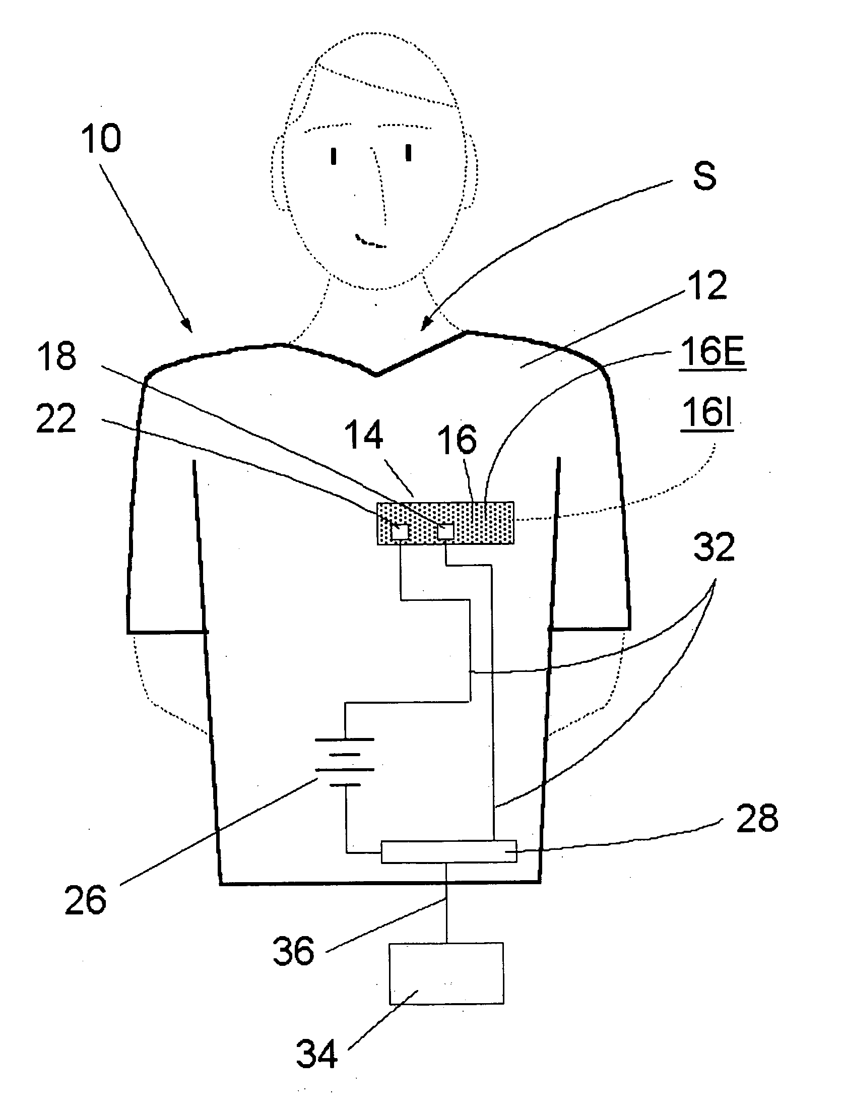
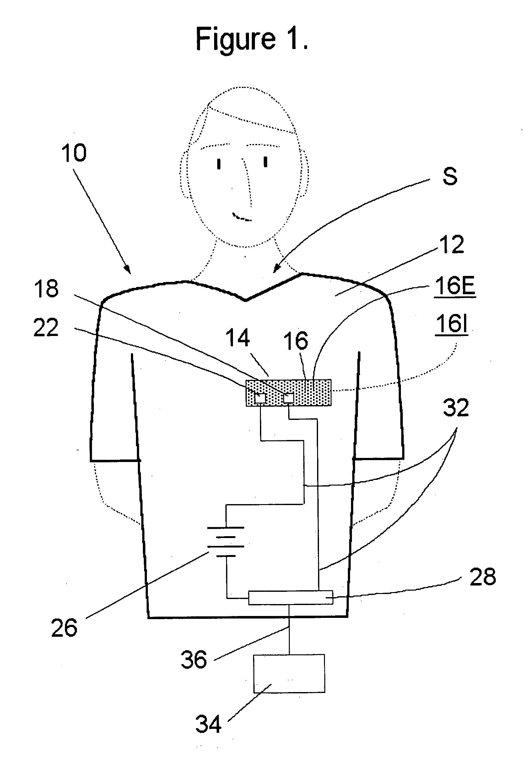
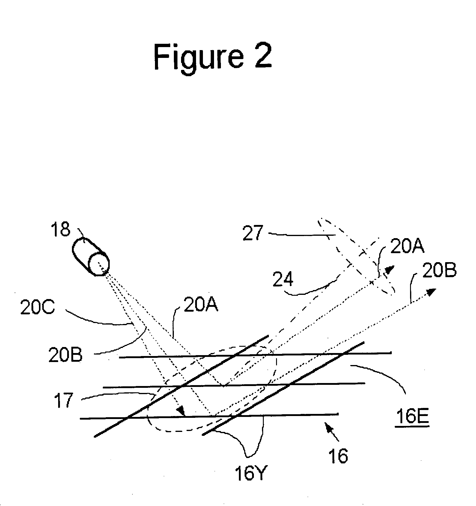
[0035]FIG. 1 is a stylized pictorial representation of a motion monitoring system 10 in accord with the present invention as applied to the task of monitoring motion due to geometric changes of the body of a subject S in response to physiological activity. A noninvasive measurement of one or more parameter(s) characterizing the physiological activity of the subject S, such as heart or breathing rate, may be derived by monitoring such motion(s).

[0036] As seen in FIG. 1, the system 10 includes a garment 12 having at least a portion, or patch 14, formed from a monitoring fabric 16. The monitoring fabric 16 has an exterior or outer surface 16E presented to a viewer and an interior surface 16I presented to the body of the subject S. The patch 14 of the monitoring fabric 16, although shown as rectangular in FIG. 1, may take any convenient shape. For ...


PUM

PropertyMeasurementUnit
wavelengthaaaaaaaaaa

Abstract

A garment and system includes a monitoring fabric that exhibits a light reflection property and substantially no light transmission property when the fabric is illuminated with light having wavelength(s) in the range of 400 to 2200 nanometers. The amount of useful light reflected by the fabric into an aperture of acceptance defined with respect to an axis extending from the fabric relative to the amount of light lost to the aperture of acceptance detectably changes when the fabric stretches in response to motion, as the motion induced by physiological activity (e.g., heart rate). The system includes at least one radiation source and at least one radiation detector, with the detector disposed in the aperture of acceptance. The source and detector may be attached to the fabric in relative positions such that the reception of incident radiation by the detector is directly affected by a change in the amount of useful light reflected by the fabric into the aperture of acceptance as the fabric stretches in response to motion.

Description

CROSS-REFERENCE TO RELATED APPLICATIONS [0001] Subject matter disclosed herein is related to the following co-pending applications: [0002] System for Monitoring Motion of a Member, U.S. application Ser. No. 60 / 502,760; (LP-5345USPRV), filed Sep. 11, 2003 in the name of Chia Kuo and George W. Coulston. [0003] Blood Pressure Monitoring System and Method, U.S. application Ser. No. 60 / 502,751; (LP-5347USPRV), filed Sep. 11, 2003 in the names of George W. Coulston and Thomas A. Micka. [0004] Reflective System for Monitoring Motion of a Member, U.S. application Ser. No. 60 / 502,750; (LP-5346US PRV), filed Sep. 11, 2003 in the name of George W. Coulston; [0005] Blood Pressure Monitoring System and Method Having Extended Optical Range, U.S. application Ser. No. 60 / 526,187; (LP-5622USPRV), filed Dec. 2, 2003 in the names of George W. Coulston and Thomas A. Micka. [0006] Extended Optical Range Reflective System for Monitoring Motion of a Member, U.S. application Ser. No. 60 / 526,429; (LP-5621 U...

Claims


Application Information

Patent Timeline
Patent Type & Authority Applications(United States)
IPC IPC(8): A41D13/12A61B5/02A61B5/022A61B5/024A61B5/11A61B5/113D04B1/14D03D15/56G01L1/24
CPCA41D13/1281A61B5/022A61B5/02233A61B5/02416A61B5/02438D04B1/14A61B5/1126A61B5/1128A61B5/1135A61B5/6804A61B5/6805A61B5/02444D10B2403/02431Y10T442/30Y10T442/3976Y10T442/3024Y10T442/413Y10T442/3382Y10T442/40Y10T442/3008A61B5/00
Inventor COULSTON, GEORGE W.
Owner ADIDAS
Why Eureka
Try Eureka