
Camera-equipped cellular phone

Inactive Publication Date: 2005-05-19
KYOCERA CORP
View PDF9 Cites 35 Cited by
  • Summary
  • Abstract
  • Description
  • Claims
  • Application Information

AI Technical Summary

Benefits of technology

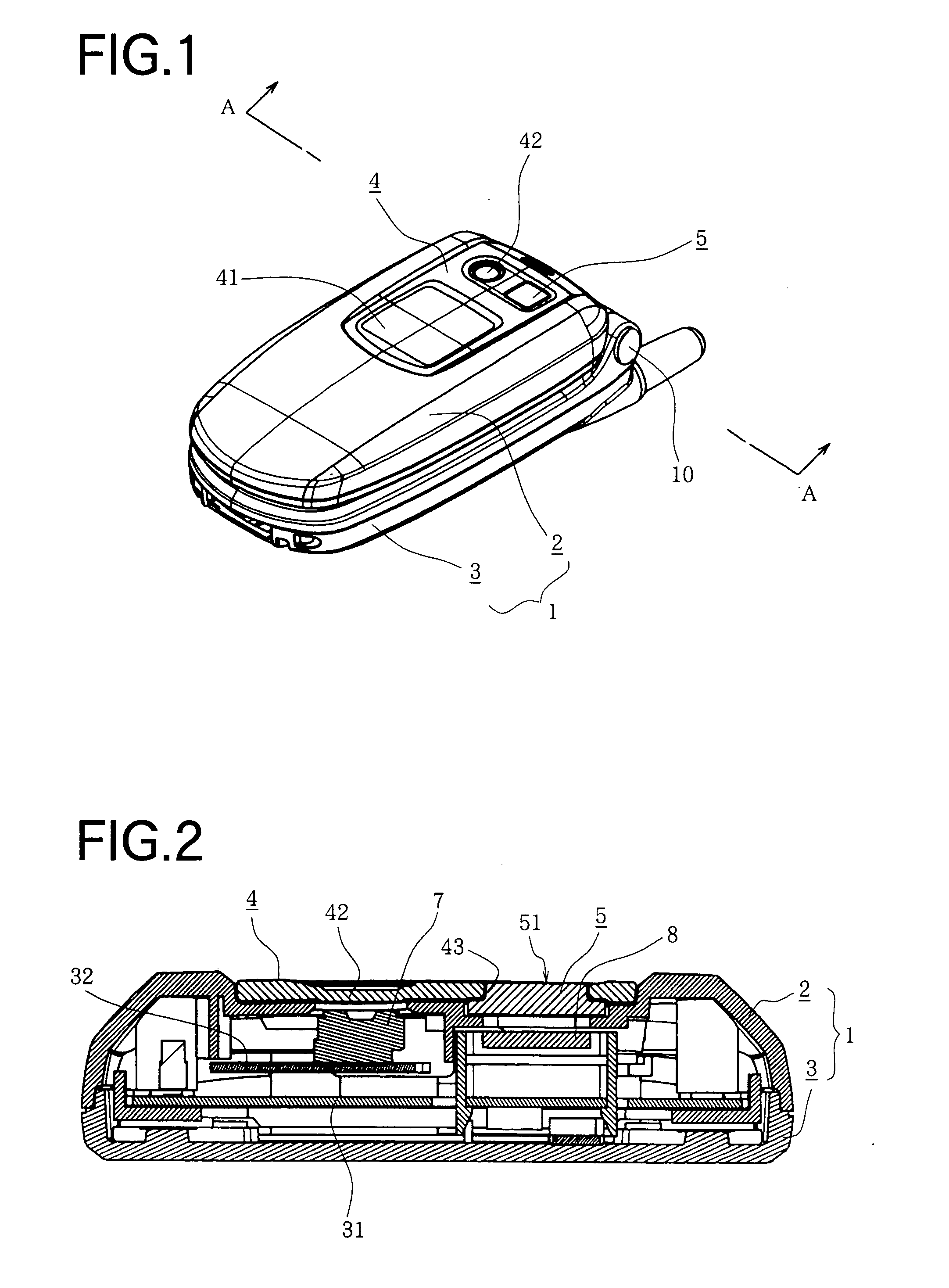
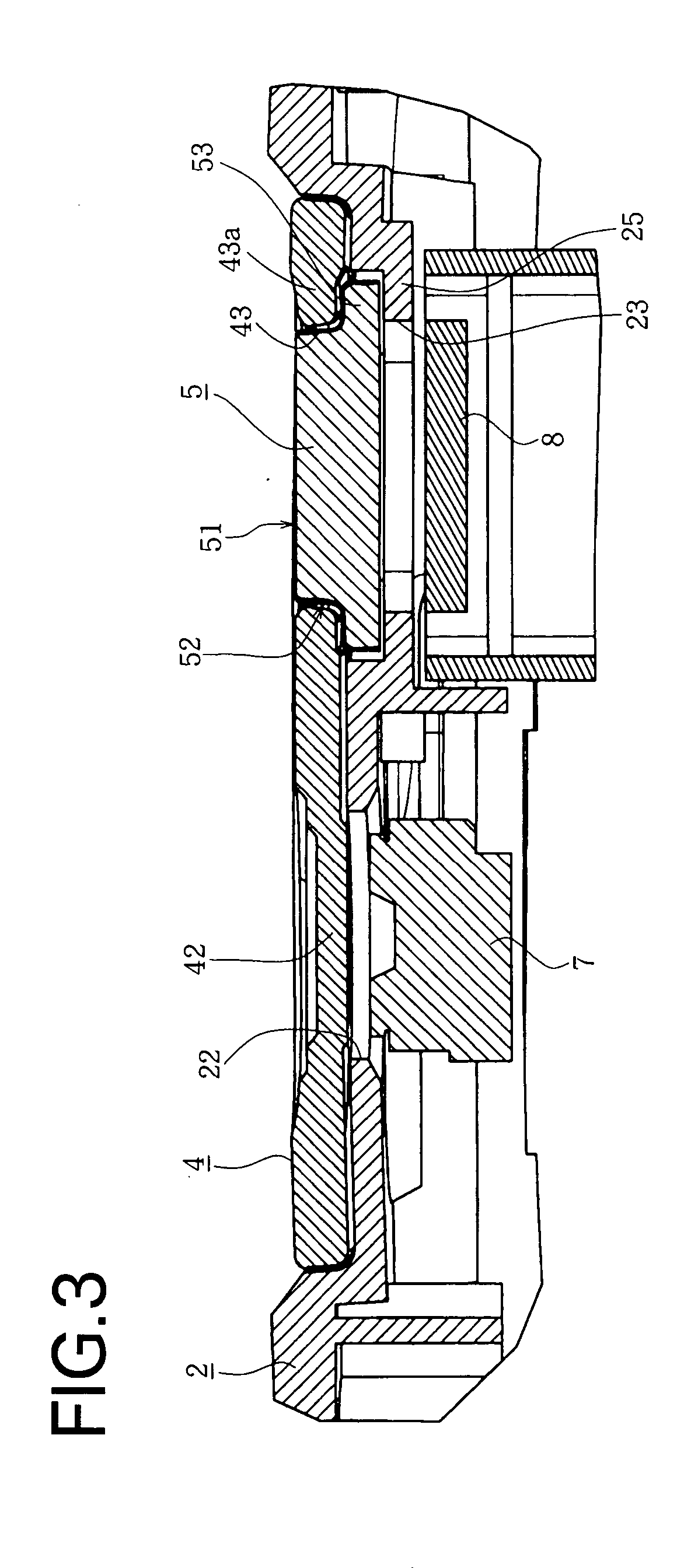
[0008] Stated specifically, the main optical cover 4 is formed with an opening 43 for mounting the auxiliary optical cover 5. An outer peripheral surface of the auxiliary optical cover 5 or an inner peripheral portion of the opening 43 of the main optical cover 4 is given light-shield treatment to provide said light-shield surface. According to the specific construction, the auxiliary optical cover 5 is fitted around the opening 43 of the main optical cove 4 to provide one optical cover. The light emission to the inside of the auxiliary optical cover 5 is, however, shielded by the light-shield surface, so that the light does not leak out to the inside of the main optical cover 4.
[0009] Stated further specifically, the optical cover formed with the light-shield surface comprises a transparent optical cover main body portion 54 made of a first synthetic resin and an outer periphery layer portion 55 which is formed on an outer peripheral surface of the main body portion 54 and made of a second synthetic resin. An outer peripheral surface of the outer periphery layer portion 55 is selectively plated with metal, and is thereby given the light-shield treatment. According to the specific construction, the light-shield surface can be easily formed by double injection molding and electroless plating as conventionally known.
[0010] As described above, the portable telephone with camera of the present invention is adapted to prevent the degradation of picture quality caused by the arrangement of the camera and the auxiliary light source in the close proximity.

Problems solved by technology

However, the conventional portable telephone with camera has the problem that when a picture is taken with the CCD camera in the dim light, natural light does not provide sufficient brightness to make the taken image unclear.
In this case light emanating from the auxiliary light source in part is reflected in the optical cover to impinge on the CCD camera, causing halation.
Consequently there rises the problem of degradation of picture quality of an image photographed with the CCD camera due to the halation.

Method used


Image

  • Camera-equipped cellular phone
  • Camera-equipped cellular phone
  • Camera-equipped cellular phone

Examples


Embodiment Construction

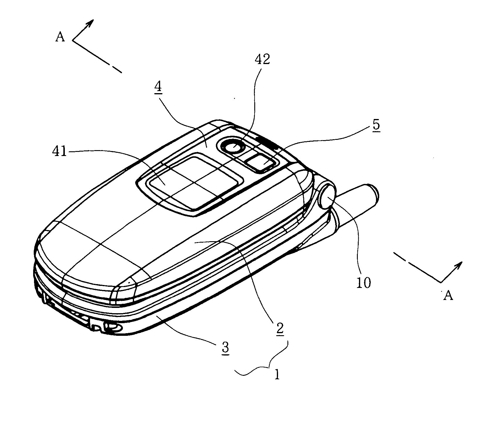
[0020] The embodiment of the present invention will be described below in detail with reference to the drawings. The portable telephone with camera of the present invention comprises an upper half case 2 and lower half case 3 which are connected by a hinge mechanism 10 to provide a foldable portable telephone as shown in FIG. 1. A main board 31 and sub-board 32 are installed inside a casing 1 as shown in FIG. 2.

[0021] Mounted on the main board 31 is a liquid crystal display 6 serving as an auxiliary display as shown in FIG. 4. Mounted on the sub-board 32 are a CCD camera 7 and an auxiliary light source 8 comprising LED. Provided on the upper half case 2 are a display window 21 for exposing the liquid crystal display 6, a camera window 22 for exposing the CCD camera 7, and an auxiliary light window 23 for exposing the auxiliary light source 8.

[0022] Mounted on the upper half case 2 are a main optical cover 4 for closing the display window 21 and the camera window 22, and an auxilia...


PUM


Abstract

The present invention provides a portable telephone with camera having a camera 7 mounted as opposed to a camera window 22 provided on a casing. The casing is provided with an auxiliary light window 23 adjacent to the camera window 22. Arranged in the rear of the auxiliary light window 23 is an auxiliary light source 8 for emitting light in photographing with the camera 7. The camera window 22 is covered with a main optical cover 4. The auxiliary light window 23 is covered with an auxiliary optical cover 5. A light-shield surface 52 is formed between the main optical cover 4 and the auxiliary optical cover 5. Consequently the degradation of picture quality when the camera 7 and the auxiliary light source 8 are arranged close to each other is prevented.

Description

TECHINICAL FIELD [0001] The present invention relates to portable telephones integrally equipped with a camera to allow the user to take a picture. BACKGROUND ART [0002] In recent years portable telephones with camera have been in wide use. For example, a portable telephone with camera shown in FIG. 9 comprises an upper half case 20 and lower half case 30 which are connected by a hinge mechanism 104 to provide a foldable portable telephone. An auxiliary display 101 and a camera window 102 are disposed on an outer surface of the upper half case 20. A CCD camera (not shown) is provided in the rear of the camera window 102. Furthermore, arranged in a side portion of the camera window 102 on an outer surface of the upper half case 20 is a mirror member 103 for projecting the user's self image thereon to thereby adjust the direction of the camera when the user is to photograph the user's self image. [0003] However, the conventional portable telephone with camera has the problem that when...

Claims


Application Information

Patent Timeline
IPC IPC(8): H04M1/02H04M1/21H04N5/225H04W88/02
CPCH04N5/2251H04N2007/145H04N5/2256H04M1/0264H04N23/56H04B1/40H04N23/00
Inventor MAKINO, MASAMI
Owner KYOCERA CORP
Learn More