
Cleaning device for cleaning pipes and receptacles

a cleaning device and a technology for receptacles, applied in the direction of cleaning devices for boards, cleaning brushes, low-profile cleaning, etc., to achieve the effect of preventing a deflection of the cleaning head and a small force expenditur

Inactive Publication Date: 2005-05-26
GROEBEL MICHAEL
View PDF10 Cites 11 Cited by
  • Summary
  • Abstract
  • Description
  • Claims
  • Application Information

AI Technical Summary

Benefits of technology

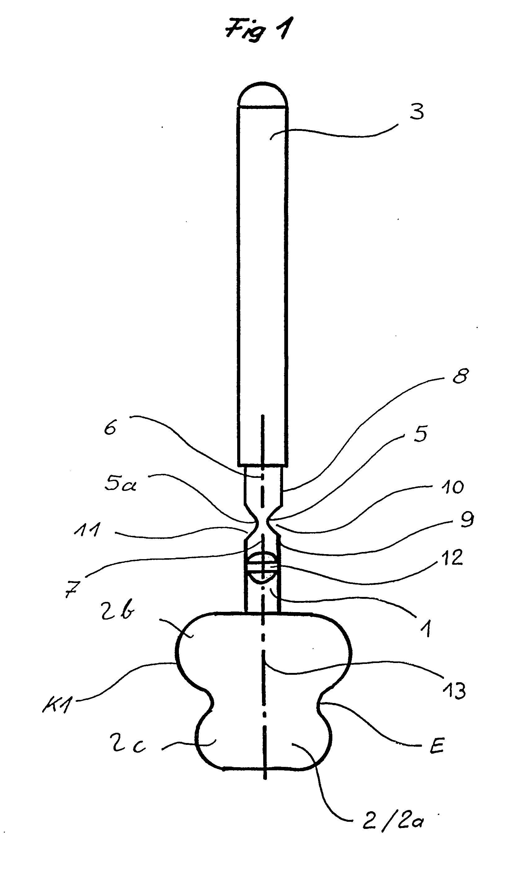
[0032] The projection and / or the reduced diameter section enables the cleaning elements to reach into the undercut of the object that is to be cleaned, whereby in this connection, due to the rotational symmetry of the cleaning head, a rotational movement can be transferred from the hand, via the handle, to the cleaning head. This acts as an assisting cleaning movement during the cleaning of undercuts. As a result, it is possible to undertake a more thorough cleaning in hygienically problematic zones, for example of toilet bowls.
[0033] By forming the cross-sectional reduction or reductions in a monolithic form on the cleaning head, post or handle, there result on the cleaning device movable regions up to the universal joint without having to produce and mount an additional device, for example in the form of a joint. This movable region, in the form of a cross-sectional reduction, is carried out in a single operation along with the production of the body of the cleaning head or the handle, and thus requires no further production expenditure, no further assembly, and no further material. As a result, minimal production expenditure at minimal utilization of resources is made possible.
[0034] Furthermore, due to two cross-sectional reductions, which are rotated or offset relative to one another by 90°, it is possible, in contrast to the heretofore known movable cleaning devices, to have a loss-free transfer of force in the form of rotational movement, even in an angled state, for example during the cleaning of curvatures. The assisting cleaning movement that is used in this connection enables a more thorough cleaning in hygienically problematic zones, for example at the drains of toilet bowls.
[0035] A further advantage of the invention is that the joint that is formed on the cleaning head, post or handle can, if necessary, be blocked by a tube or hollow profiled member that can be shifted or slipped over the cleaning device, and prevents a deflection of the cleaning head transverse to the longitudinal axis of the cleaning device when a force is introduced transverse to the longitudinal axis. Due to this now rigid transfer of force, a linear or curved cleaning movement is possible along the undercut of the object that is to be cleaned accompanied by a simultaneously combinable and introducible rotational movement without an undesired and uncontrollable deflection of the cleaning head.
[0036] Due to the respective position of the hollow profiled member, the cleaning device can be adapted in a more precise manner to the requirements of the respective shapes that are to be cleaned, thus enabling a cleaning with little expenditure of force.
[0038] In order, with the previously described embodiments of the cleaning devices, to prevent dirt particles and the like from depositing on the joint, especially at the corners, edges and material recesses, the outer contour and geometry of the joint region can be filled with an elastic material and can thereby be made smooth. This can be effected in a single operation, for example via a two-component injection molding.

Problems solved by technology

In this situation, it is expedient for economical reasons to dispose the joints on the cleaning head, so that they can also be replaced along with the cleaning head since they are also subjected to significant wear due to increased mechanical stresses.

Method used


Image

  • Cleaning device for cleaning pipes and receptacles
  • Cleaning device for cleaning pipes and receptacles
  • Cleaning device for cleaning pipes and receptacles

Examples


second embodiment

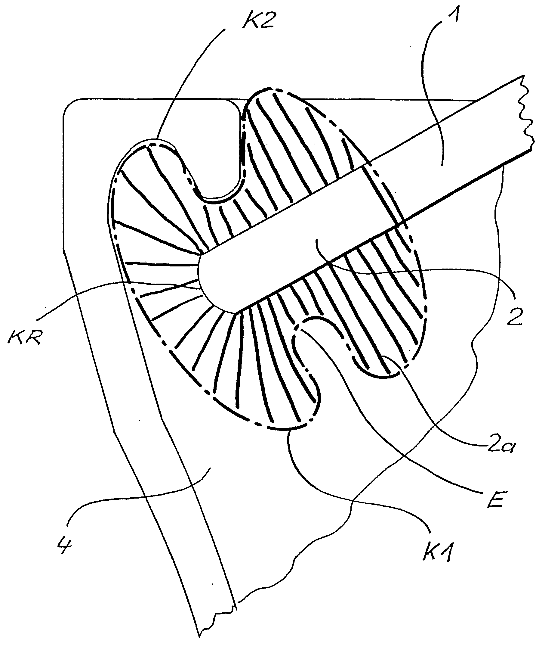
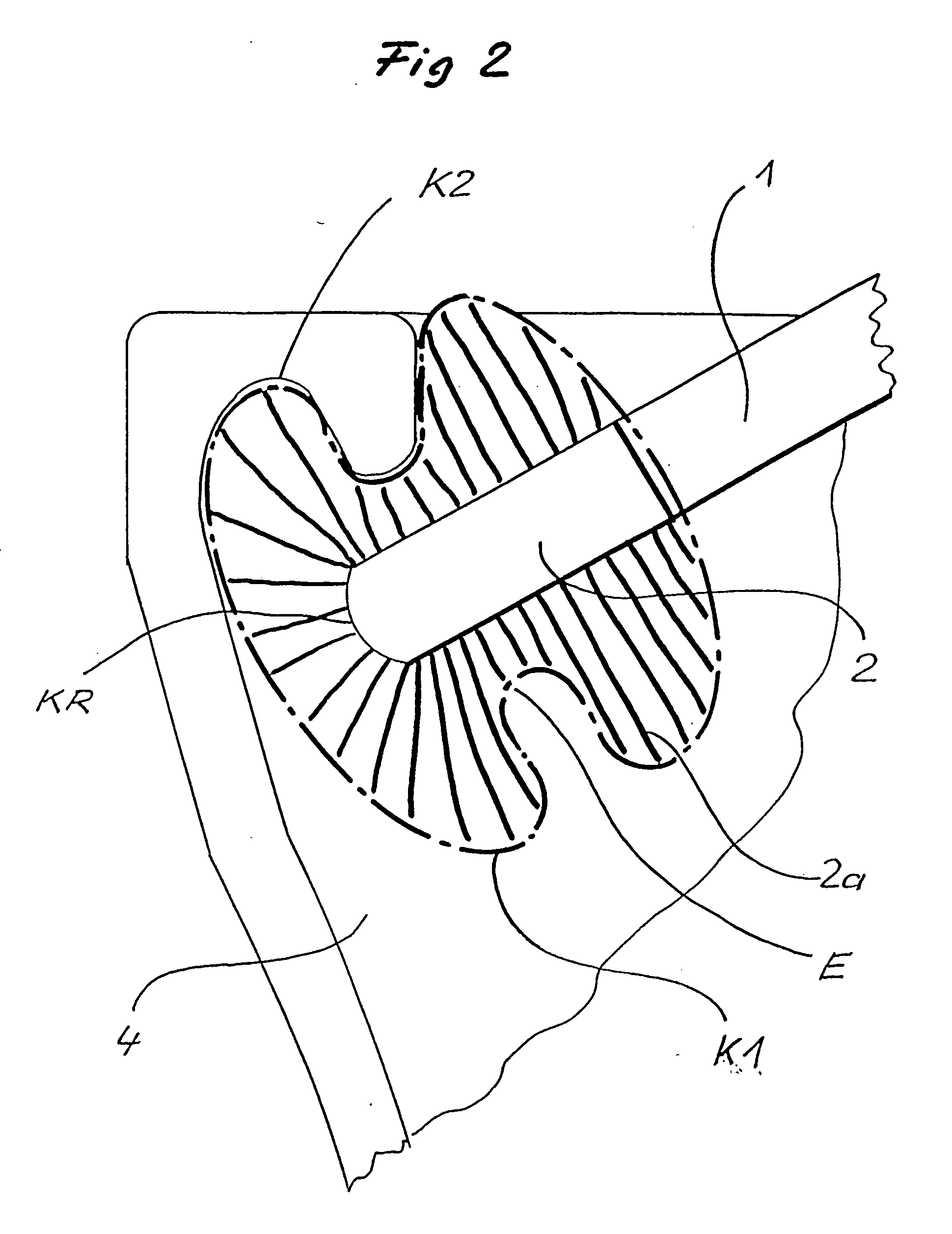
[0042]FIG. 2 shows a longitudinal section through the lower portion of an inventive cleaning device, having a circumferentially recessed outer cleaning contour K1, during the cleaning of a toilet bowl having the contour K2.

third embodiment

[0043]FIG. 3, in a view similar to FIG. 2, shows a third embodiment during the cleaning of a toilet bowl, whereby the cleaning head 2 has a set of bristles 2a that has a circumferential projection V. Not only a cleaning head having a circumferential constriction E but also a circumferential projection V is particularly suitable for extending into the contour K2 of the toilet bowl in order to free surfaces there of dirt.

[0044]FIG. 4 shows a portion of the shaft of a cleaning head 2 or a portion of the post 1 in which a joint is formed. The joint is formed by a cut out or recess in the material. Due to the mechanical weakening of the material, the shaft or post can be bent at this location, as a result of which the handle region and the cleaning head of the cleaning device can be moved relative to one another.

[0045]FIG. 5 shows a shaft or a post 1 having two joints that are disposed next to one another and are staggered by 90° relative to one another, thereby providing a further degr...


PUM


Abstract

A cleaning device is provided for cleaning pipes and receptacles. A handle is disposed on one end of the post, and a cleaning head is disposed on the other end. The cleaning head has at least one cleaning element. The cleaning head has a longitudinal section with an outer contour that is rotationally symmetrical to the longitudinal axis of the cleaning head. At least a portion of the outer contour has a circumferential projection and / or a reduced diameter section.

Description

BACKGROUND OF THE INVENTION [0001] The present invention relates to a cleaning device for cleaning pipes and receptacles, especially toilet bowls. [0002] To illustrate the features of the present invention, the function thereof will be explained in connection with the cleaning of toilet bowls. [0003] Manual devices are known for cleaning pipes, containers, for example even bottles, but also sanitary mechanisms, especially toilet bowls. In their simplest form, these known devices comprise a cleaning head, which is preferably provided with bristles, and has a handle. [0004] The upper edge of a toilet bowl generally has undercuts, as well as bends and curves in the region of the drain. [0005] Based thereon, cleaning devices have been developed, for example, that in portions of the cleaning head follow the contour of undercuts (DE 43 45 101 A1). Furthermore, cleaning devices were developed that by means of movable zones between cleaning head and handle can follow a curvature (G 92 03 56...

Claims


Application Information

Patent Timeline
Patent Type & Authority Applications(United States)
IPC IPC(8): A46B9/02A47K11/10
CPCA46B9/02A47K11/10A46B2200/3013A46B2200/3006
Inventor GROBBEL, MICHAELHELERMANN, OLIVER
Owner GROEBEL MICHAEL
Learn More