Load-resisting truss segments for buildings

a truss and building technology, applied in the direction of girders, joists, portal frames, etc., can solve the problems of high construction cost, labor-intensive installation process, and shear loads, and achieve the effect of increasing the strength of the truss pla

Active Publication Date: 2005-05-26
TRUSSED
View PDF17 Cites 19 Cited by
  • Summary
  • Abstract
  • Description
  • Claims
  • Application Information

AI Technical Summary

Benefits of technology

[0022] In another aspect, the present invention provides a load-resisting segment of a building structure, comprising a plurality of beams joined together to form a rigid framework, and a truss plate having a side secured to a side of the framework. The truss plate secures connections between two or more of the beams. The sid

Problems solved by technology

Shear loads often result from winds, earthquakes, and the like.
This configuration is expensive because it requires a great deal of plywood and the installation process is labor-intensive.
Another disadvantage of this configuration is that the nails often fail and inaccurate nailing is the cause of many lawsuits against building contractors.
The nails often miss the studs or are nailed too far into the plywood, thus causing the wall segment to lose some of the lateral load-resistin

Method used


Image

  • Load-resisting truss segments for buildings
  • Load-resisting truss segments for buildings
  • Load-resisting truss segments for buildings

Examples


Embodiment Construction

[0046] While described below primarily in the context of walls, skilled artisans will readily appreciate that the teachings of the present invention can be extended to other building portions, including floors, ceilings, roofs, and the like. Thus, the invention is not limited to components for use within walls, but also includes components for use within floors, ceilings, roofs, and the like.

[0047] The present invention provides the wood construction industry with prefabricated wall components that can be easily assembled into the building structure on a construction site. The wall components of the invention advantageously utilize truss plates and wood framing to provide a stronger lateral load-resisting wall segment than those of the prior art.

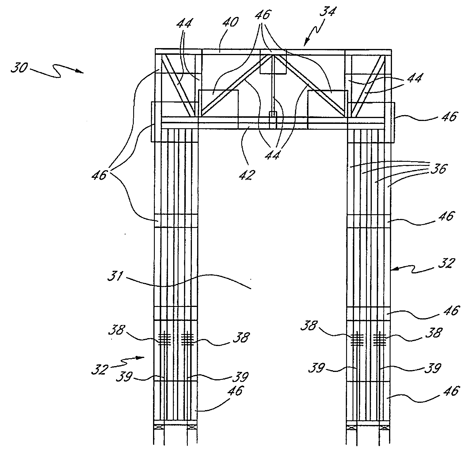
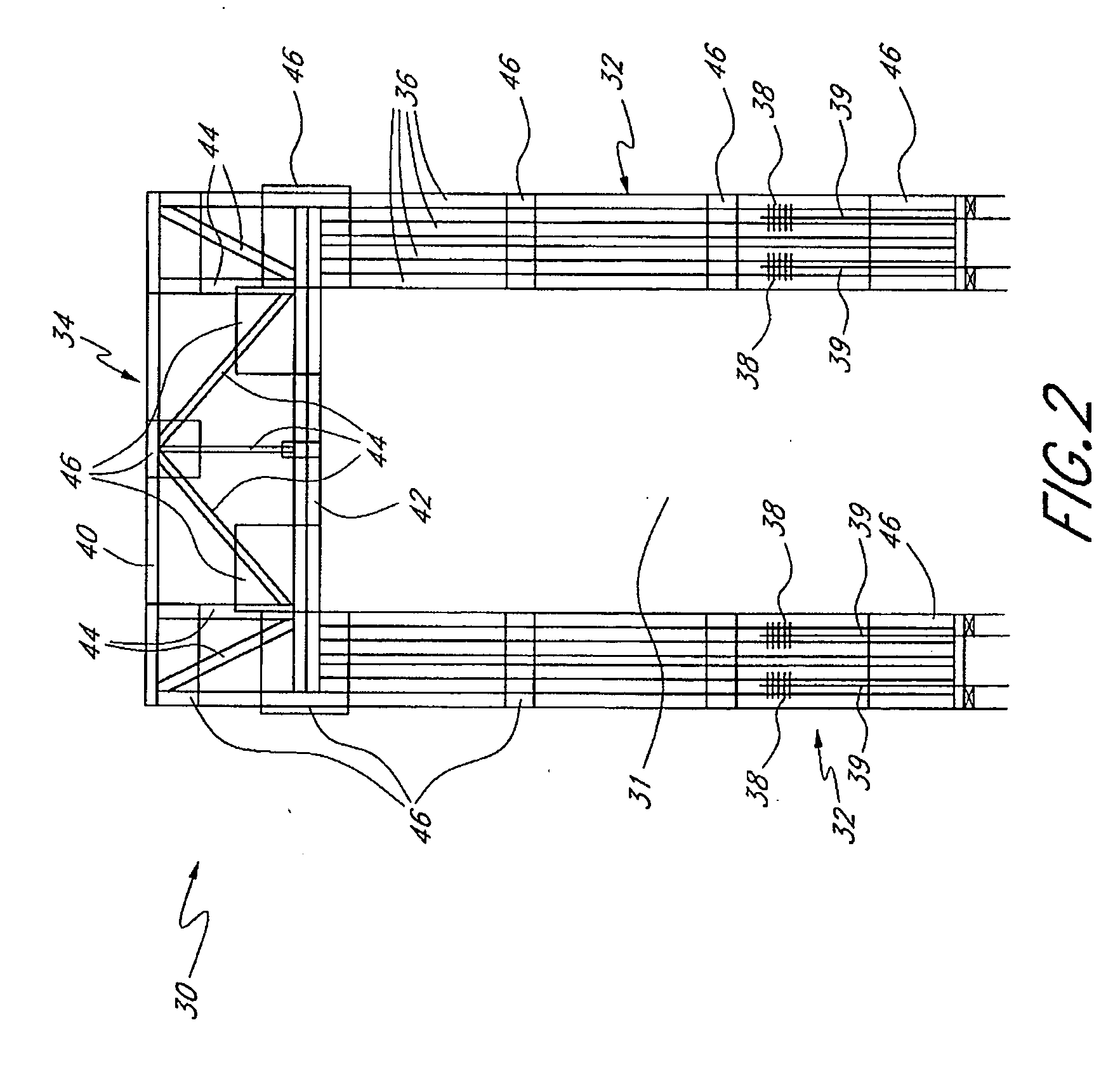
Truss Frames for Wall Openings

[0048]FIGS. 2-11 depict lateral load-resisting frame structures suitable for doors, windows, and other types of wall openings. These frame structures utilize plates for strengthening the connections between ...


PUM

PropertyMeasurementUnit
Depthaaaaaaaaaa
Strengthaaaaaaaaaa
Distanceaaaaaaaaaa

Abstract

The invention provides load-resisting segments (e.g., panels or frames for openings) for transmitting loads through a building structure. In the context of a wall, the load-resisting segments transmit shear loads downward to structural elements below the wall, such as to a building foundation. The load-resisting segments may comprise a truss configuration, i.e., an assembly of members forming a rigid framework. Each load-resisting segment can include web members and pairs of truss plates secured to sides of the segment to secure connections of the web members to each other and to other members. The wall segments can include beam-separation blocks that reduce truss plate failure by spacing apart the ends of two web members bearing against a chord or post to position the intersection point of the load paths of the web members with the load path of the chord or post. Some of the truss plates can include strips of material to provide additional resistance to tearing of the truss plate due to loads experienced by the truss plate. Some of the load-resisting segments, particularly frames for doors or windows, may include compression plates that prevent point-loading of studs or chords against transversely oriented members. For example, a truss frame may include compression plates between ends of its columns and surfaces of a header or sill structure.

Description

INCORPORATION BY REFERENCE [0001] This application incorporates by reference the entire disclosures of U.S. Pat. Nos. 4,639,176 to Smith et al. (hereinafter “the '176 patent”) U.S. Pat. No. 5,921,042 to Ashton et al. (hereinafter “the '042 patent”), and U.S. Pat. No. 6,389,767 to Lucey et al. (hereinafter “the '767 patent”).BACKGROUND OF THE INVENTION [0002] 1. Field of the Invention [0003] The present invention relates generally to building construction and more specifically to lateral load-resisting truss segments of buildings, including segments of walls, floors, roofs, ceilings, and the like. [0004] 2. Description of the Related Art [0005] It is a well-known principle of building construction that the building must include higher-strength structural segments that resist and transfer loads. These load-transfer segments can be provided in the walls, floors, roof, ceilings, and other portions of the building. For example, the building walls typically include segments that transfer ...

Claims


Application Information

Patent Timeline
IPC IPC(8): E04B1/10E04B1/26E04C3/16E04C3/42
CPCE04B1/10E04B1/26E04B2001/2696Y10T29/49627E04C3/42E04C2003/026E04C3/16
Inventor CLOYD, KENNETH M.LUCEY, ROBERT D.
Owner TRUSSED
Why Eureka
Try Eureka