Press mechanism, clamp mechanism, and molding machine using this clamp mechanism

a technology of clamping mechanism and press plate, which is applied in the direction of mechanical control devices, instruments, applications, etc., can solve the problems of inability to maintain the the inability to control the position and pressure of the press plate with high accuracy in the vicinity of the bottom dead center, and the inability to maintain the highly accurate parallelism of the press plate. , to achieve the effect of high accuracy and highly accurate parallelism of the press pla

Inactive Publication Date: 2005-05-26
ITRIX CORP
View PDF9 Cites 13 Cited by
  • Summary
  • Abstract
  • Description
  • Claims
  • Application Information

AI Technical Summary

Benefits of technology

[0013] This invention has been attained in view of the foregoing, and its object is to provide a press mechanism, a clamp mechanism and a molding machine using this clamp mechanism in which the position and pressure of a press plate can be controlled with high accuracy while highly accurate parallelism of the press plate is maintained.

Problems solved by technology

The toggle device shown in FIG. 5 of the description of Patent No. 3159450 mentioned above can produce comparatively great torque and can have a great moving stroke of the press plate, but its problem is that the position and pressure of the press plate cannot be controlled with high accuracy in the vicinity of the bottom dead center.
Furthermore, the problem of the two-stage driving leverage shown in FIG. 1 to FIG. 4 of the description of Patent No. 3159450 is that, because the action point to act on the press plate is provided closer to one end of the lever member, torsional stress functions when the two drive sources are used to urge the press plate such that highly accurate parallelism of the press plate cannot be maintained.
With such large movement of the force point, the lever member pivots greatly, and undesirable stress acts on the lever member along its longitudinal direction, thus making it impossible to maintain the highly accurate parallelism of the press plate.
Further yet, in this leverage, one drive source urges the force point to pivot the lever member, so that if a drive source is used which is suitable for moving the press plate with a great stroke, the position and pressure of the press plate cannot be controlled with high accuracy.

Method used


Image

  • Press mechanism, clamp mechanism, and molding machine using this clamp mechanism
  • Press mechanism, clamp mechanism, and molding machine using this clamp mechanism
  • Press mechanism, clamp mechanism, and molding machine using this clamp mechanism

Examples


Embodiment Construction

[0034] Embodiments of this invention will hereinafter be described in detail with reference to the drawings.

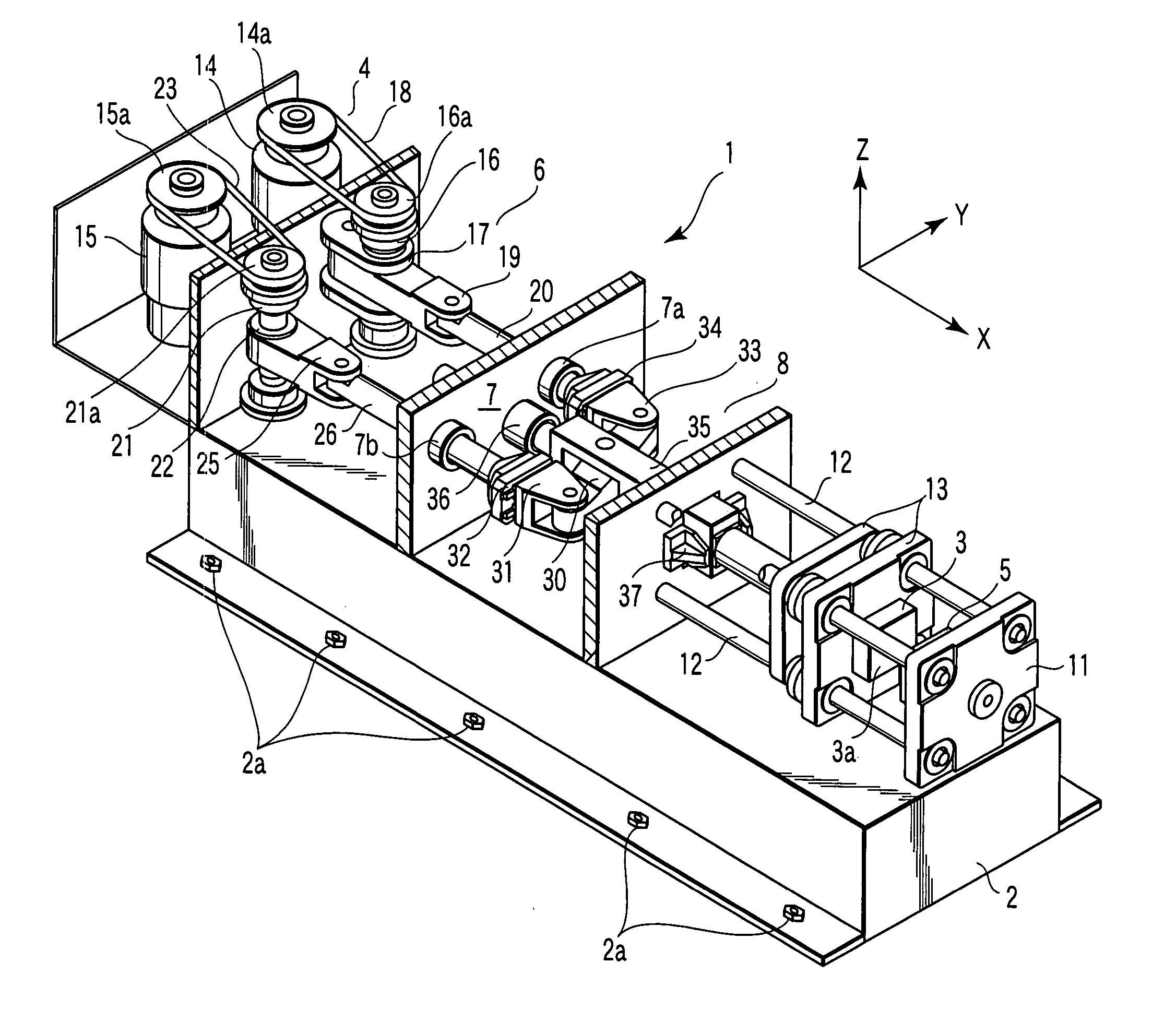
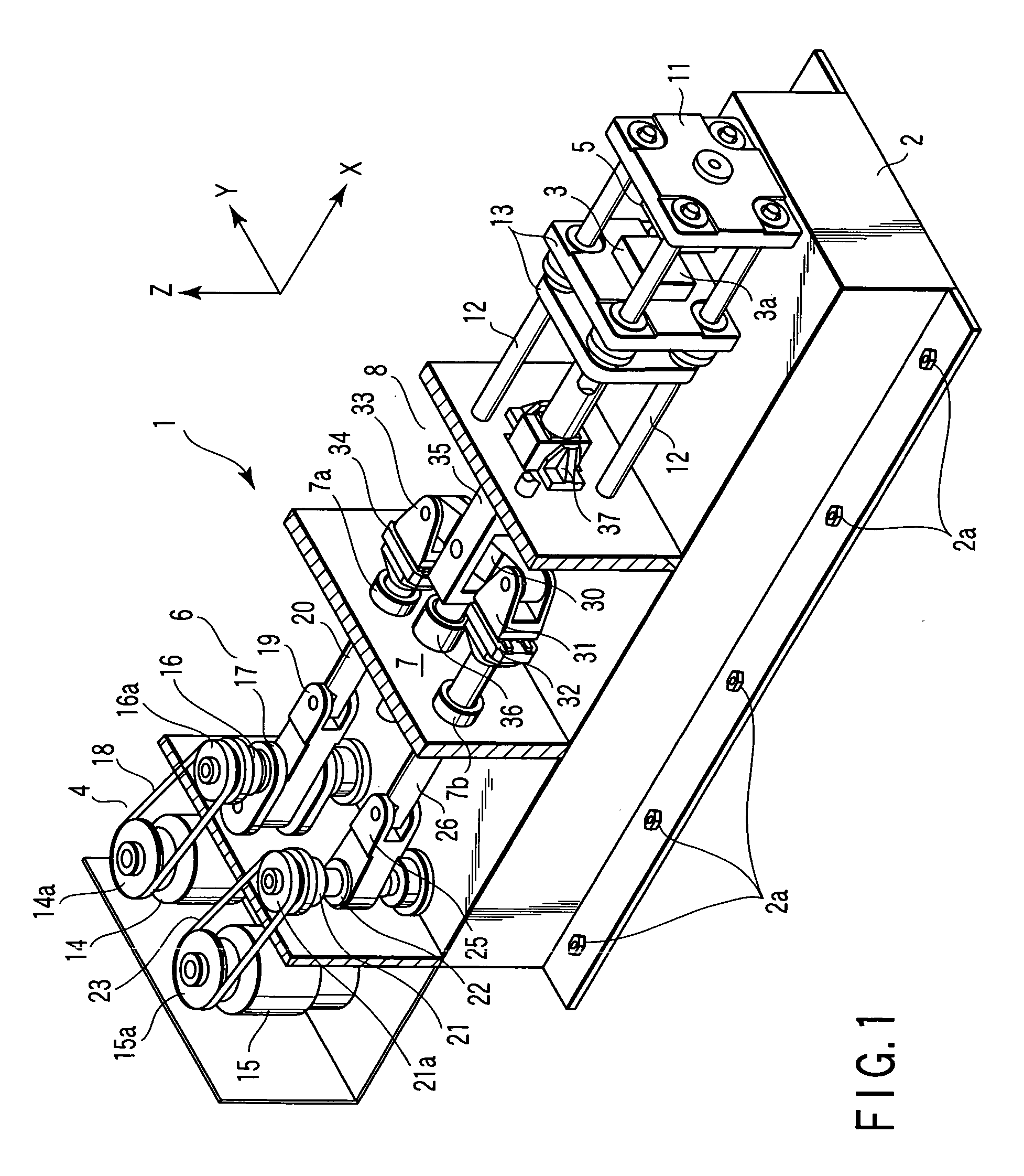
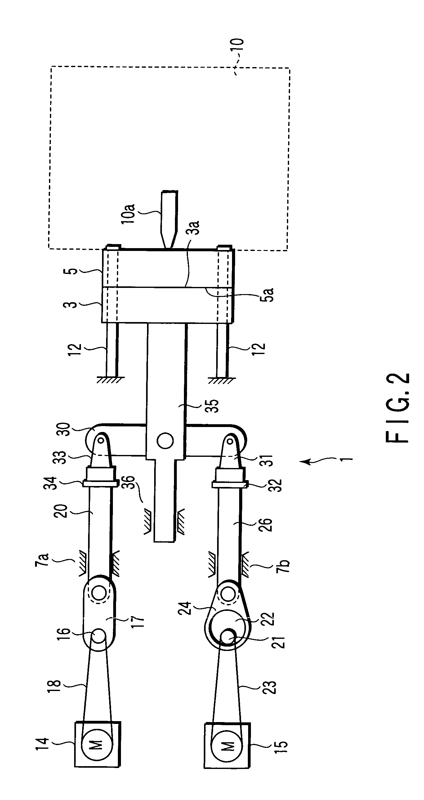
[0035]FIG. 1 is a schematic perspective view of a plastic injection molding machine 1 (hereinafter referred simply as an injection molding machine 1) which functions as a molding machine according to embodiments of this invention. FIG. 2 is a schematic plan view of this injection molding machine 1. In FIG. 1, a frame 2 of the injection molding machine 1 is shown in a partially disassembled state for clarity in the drawing, and an injection device 10 (see FIG. 2) which will be described later is not shown.

[0036] As shown in FIG. 1, the frame 2 (case) of the injection molding machine 1 is fixed to level ground by a plurality of stud bolts 2a (and nuts). The frame 2 integrally has a plurality of partitions which divide into a motor chamber 4, a crank chamber 6 and a lever chamber 8, along a driving direction (arrow X direction in the drawing; hereinafter referred to as an X dir...


PUM

PropertyMeasurementUnit
moving distanceaaaaaaaaaa
thicknessaaaaaaaaaa

Abstract

A thermal pressing machine has a case in which a fixed-side press plate is fixedly provided, a main shaft to which a moving side press plate is attached, a lever arm pivotally attached to the main shaft, a first drive mechanism coupled to a force point at one end of the lever arm, and a second drive mechanism coupled to a supporting point at the other end of the lever arm. The first drive mechanism first causes the lever arm to pivot on the supporting point to greatly move the press plate, and the first drive mechanism is then stopped to operate the second drive mechanism, so that the lever arm pivots on the force point to press the press plate against the press plate.

Description

CROSS-REFERENCE TO RELATED APPLICATIONS [0001] This is a Continuation Application of PCT Application No. PCT / JP03 / 12026, filed Sep. 19, 2003, which was published under PCT Article 21(2) in Japanese. [0002] This application is based upon and claims the benefit of priority from prior Japanese Patent Application No. 2002-275369, filed Sep. 20, 2002, the entire contents of which are incorporated herein by reference.BACKGROUND OF THE INVENTION [0003] 1. Field of the Invention [0004] This invention relates to a press mechanism to drive a press plate, a clamp mechanism of a molding machine which drives one die toward another die, and a molding machine comprising this clamp mechanism. [0005] 2. Description of the Related Art [0006] In a press mechanism or a clamp mechanism of a molding machine, a toggle mechanism using, for example, a lever has heretofore been used as a mechanism to drive a press plate (refer to, for example, FIG. 5, description of Patent No. 3159450). The toggle mechanism ...

Claims


Application Information

Patent Timeline
Patent Type & Authority Applications(United States)
IPC IPC(8): B29C33/20B29C33/22B29C45/66B30B1/06
CPCB29C33/22B29C45/66B29C2045/1792Y10T74/20582B30B1/06Y10T74/206B29C2045/664
Inventor HASEGAWA, SHOJI
Owner ITRIX CORP
Why Eureka
Try Eureka