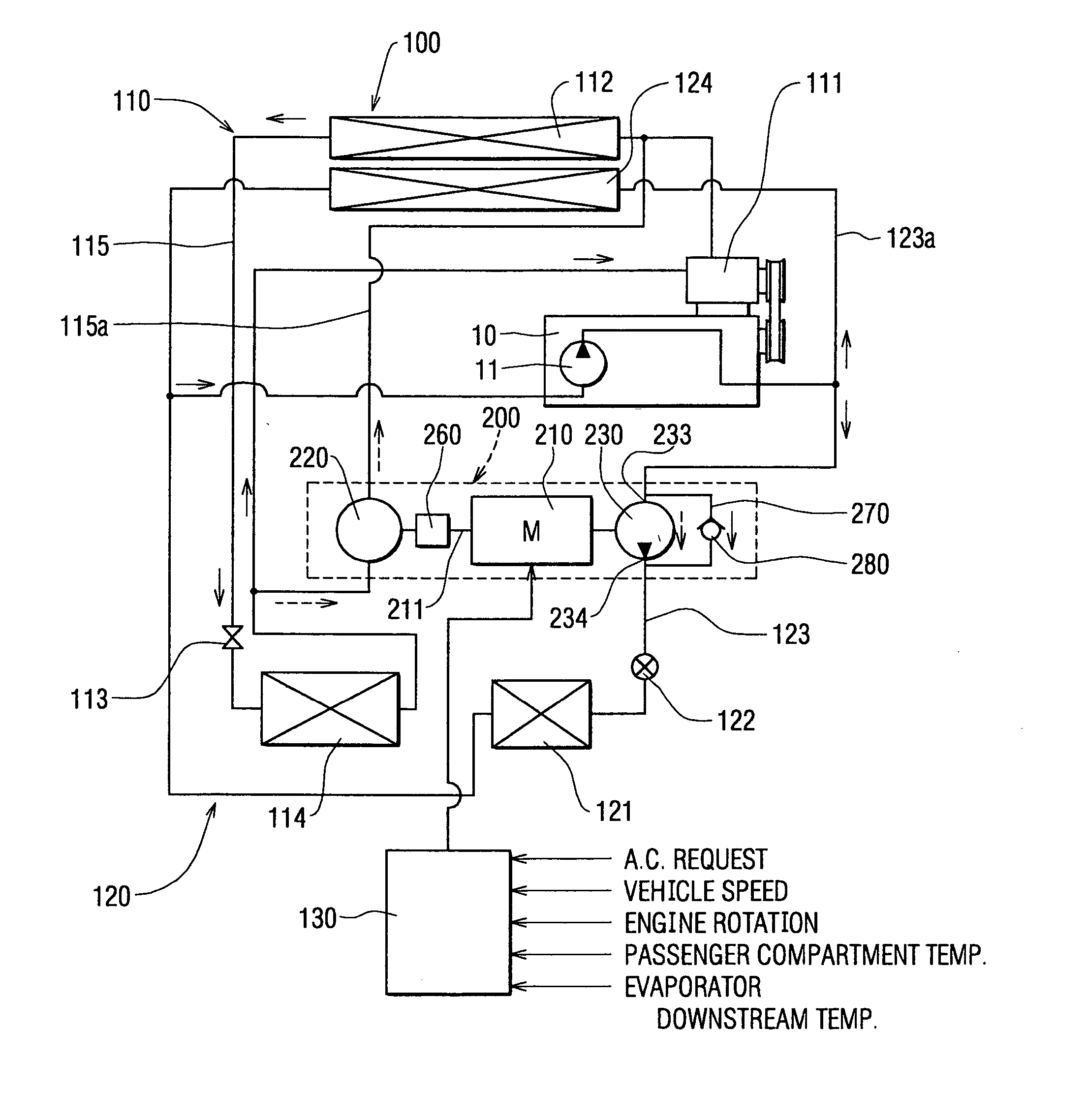
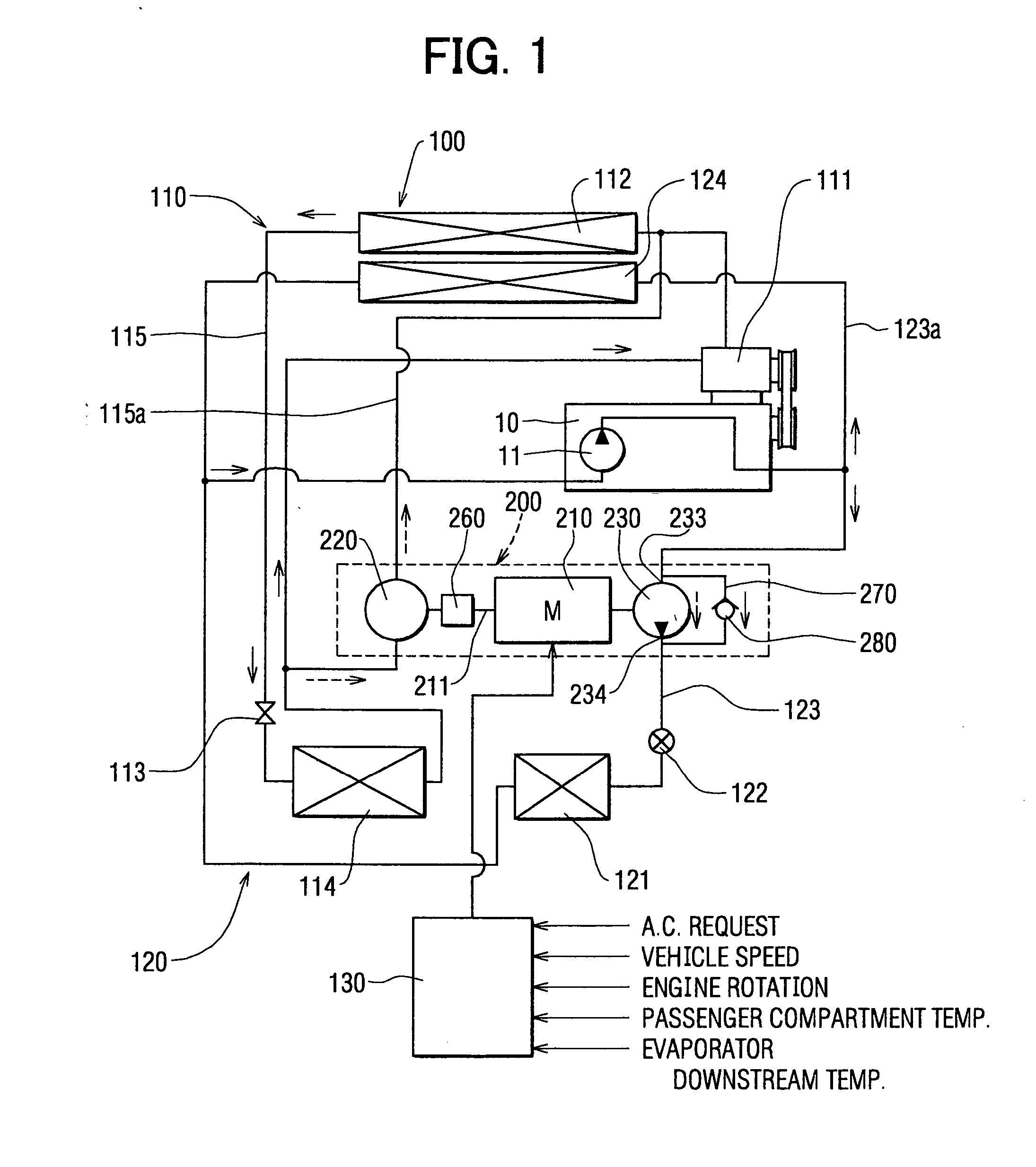
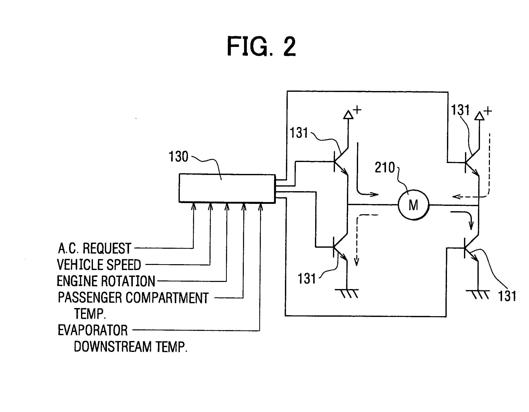
Air-conditioning apparatus including motor-driven compressor for idle stopping vehicles
a technology of air conditioning apparatus and motor, which is applied in the direction of lighting and heating apparatus, space heating and ventilation control systems, heating types, etc., can solve the problems of increasing the number of parts, insufficient devices disclosed in these publications, and complicated and expensive systems
- Summary
- Abstract
- Description
- Claims
- Application Information
AI Technical Summary
Benefits of technology
Problems solved by technology
Method used
Image
Examples
sixth embodiment
[0201]FIG. 19 shows a sixth embodiment of the present invention. The sixth embodiment differs from the fifth embodiment in that step S1102 of the control flow is changed to step S1112.
[0202] Here, instead of the motor temperature sensor 2122 arranged on the motor 2102, the control unit 1302 is provided with a timer function for keeping the operating time tm of the motor 2102. For a predetermined time period (first predetermined time period) t1, the maximum operating time per activation is previously calculated from the operating life of the motor 2102. When the operating time tm of the motor 2102 exceeds the predetermined time t1, the motor 2102 is stopped at step S902. This provides the same effects as in the fifth embodiment.
seventh embodiment
[0203]FIGS. 20-22E show a seventh embodiment of the present invention. The seventh embodiment is based chiefly on the cooling unit 1102. Before the stoppage of the engine 9102, the temperature of the evaporator 1142 is reduced in a temperature down mode, so that the evaporator 1142, when the engine 9102 is stopped, performs cooling while less power is consumed by the motor 2102. In FIG. 20, as compared to the fifth embodiment, the heating unit 1202 is omitted and the electric compressor-pump 2002 is replaced with an electric compressor 2012.
[0204]FIG. 20 shows the overall configuration of the vehicle air-conditioning system 1002, in which a fan 1142a for sending air to the evaporator 1142 is provided. The air flow rate of the fan 1142a can be adjusted by the control unit 1302.
[0205] The control unit 1302 also has an engine stoppage predicting function for predicting whether the engine 9102 will stop while the vehicle is moving. Specifically, this function is based on the vehicle s...
eighth embodiment
[0213]FIGS. 20, 21, and 23A-23F show an eighth embodiment of the present invention. The eighth embodiment is a modified variation of the seventh embodiment, in which the temperature down mode of the evaporator 1142 includes a valve opening control of the expansion valve 1132 aside from the air flow rate control of the fan 1142a.
[0214] The expansion valve 1132 in FIG. 20 is a solenoid valve that can be adjusted in valve opening by the control unit 1302. If the stoppage of the engine 9102 is predicted, the process moves to step S222 of FIG. 21 to enter the temperature down mode. Here, the air flow rate of the fan 1142a is reduced to lower the evaporator downstream temperature Te as in the seventh embodiment (FIGS. 22B and 22D). At the same time, the valve opening is reduced (FIG. 22C) so that the refrigerant flows to the evaporator 1142 at a flow rate smaller than immediately before the prediction of stoppage of the engine 9102. Incidentally, when the motor 2102 is operated, the temp...
PUM
 Abstract
Description
Claims
Application Information
 - R&D
- Intellectual Property
- Life Sciences
- Materials
- Tech Scout
- Unparalleled Data Quality
- Higher Quality Content
- 60% Fewer Hallucinations
Browse by: Latest US Patents, China's latest patents, Technical Efficacy Thesaurus, Application Domain, Technology Topic, Popular Technical Reports.
© 2025 PatSnap. All rights reserved.Legal|Privacy policy|Modern Slavery Act Transparency Statement|Sitemap|About US| Contact US: help@patsnap.com


