Oil and gas well alloy squeezing method and apparatus

a technology of alloy squeezing and gas well, which is applied in the direction of cleaning apparatus, fluid removal, insulation, etc., can solve the problems of compromising well safety, environmental problems, and often leakage of shallow gas through the casing cement used in well completion, and achieve high viscosity

Inactive Publication Date: 2005-05-26
CANITRON SYST
View PDF7 Cites 76 Cited by
  • Summary
  • Abstract
  • Description
  • Claims
  • Application Information

AI Technical Summary

Problems solved by technology

The leakage of shallow gas through the casing cement used in well completion is often a problem in oil and gas wells.
Such leakage is generally caused by inherent high pressures in oil and gas wells and can create environmental problems and compromise well safety.
This leakage most often occurs because of cracks or other imperfections that occur in the cement that is injected into the well during well completion procedures between the well casing and the wellbore.
One disadvantage in using the technique taught by Rusch et al is that high pressure differentials across the source of leakage are required.
However, the use of cement has disadvantages.
The cement used for well sealing purposes has a relatively high viscosity which limits the penetration of the cement into discontinuities both in the well formation and in the cement previously used for sealing the well.
Furthermore, cement has a partially solidified state before it finally solidifies which limits the application of pressure on the cement during the squeezing operation.

Method used


Image

  • Oil and gas well alloy squeezing method and apparatus
  • Oil and gas well alloy squeezing method and apparatus
  • Oil and gas well alloy squeezing method and apparatus

Examples


Embodiment Construction

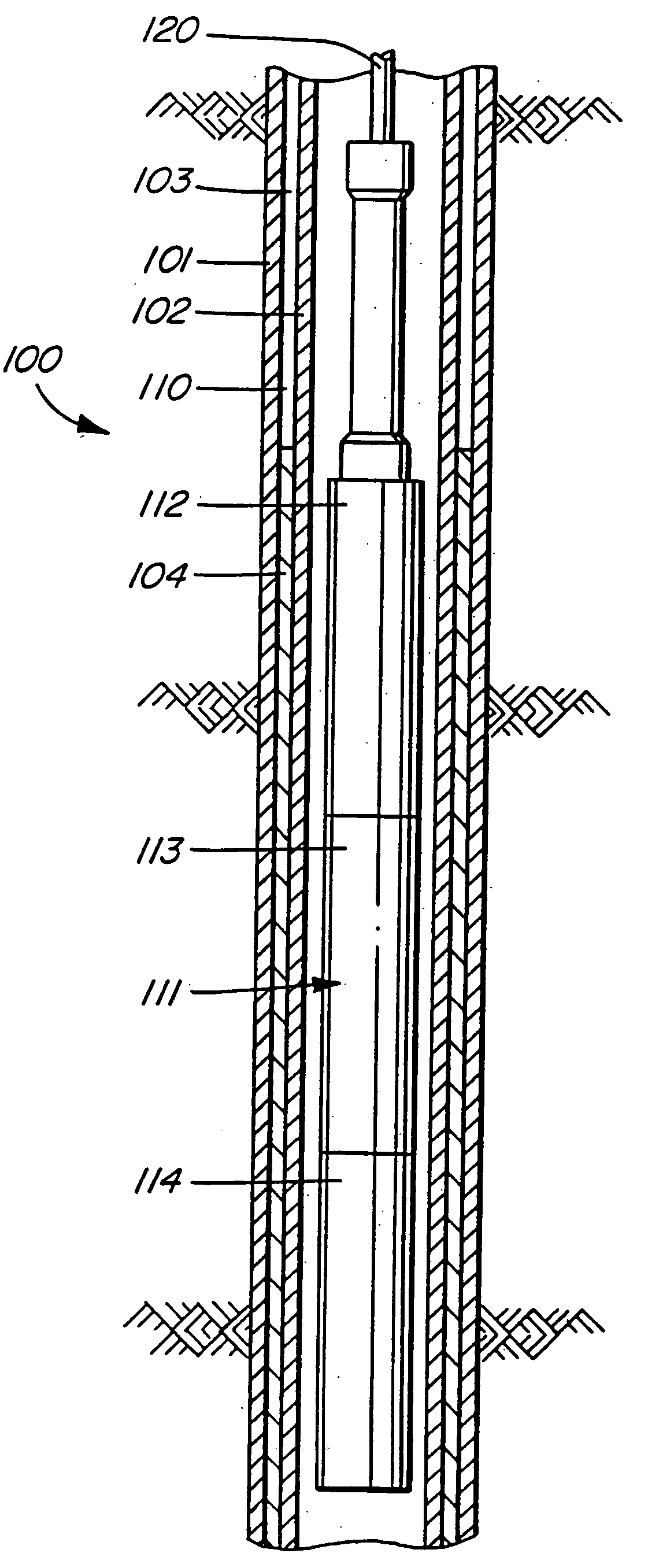
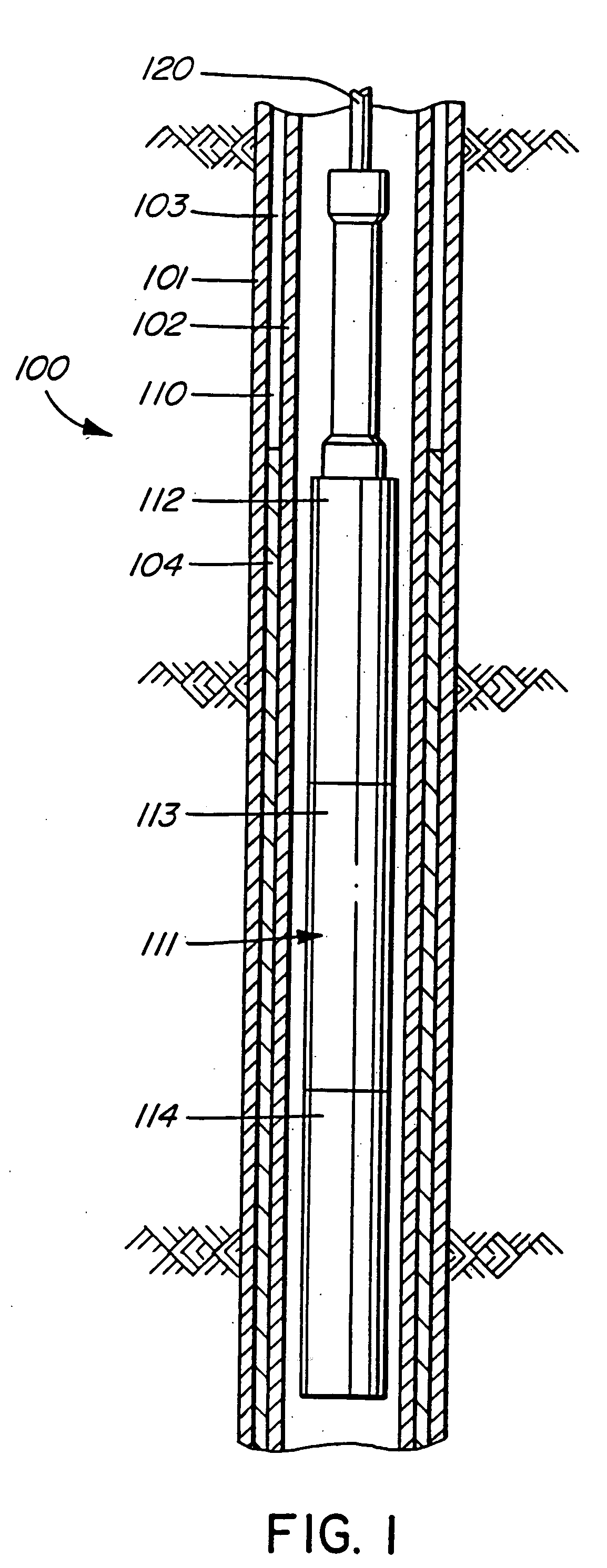
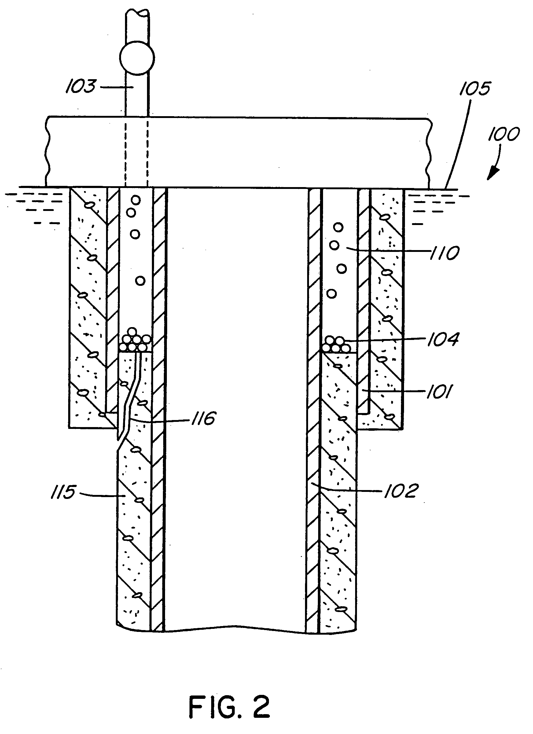
[0035] Referring now to the drawings, the surface and production casings of an oil or gas well generally illustrated at 100 are illustrated at 101, 102, respectively. The outside or surface casing 101 extends from the surface 105 (FIG. 2) of the formation downwardly and the production casing 102 extends downwardly within the surface casing 101. An annulus 110 is formed between the production and surface casings 101, 102, respectively. It will be appreciated that FIG. 2 is intended to diagrammatically illustrate an offshore well while FIG. 3 is intended to diagrammatically illustrate an onshore oil or gas well.

[0036] An injection port 103 extends downwardly from the surface into the annulus 110 between the surface and production casings 101, 102. The injection port 103 is used not only to inject certain fluids into the annulus 110 but is also used to carry small shot pellets 104 in the form of BB's which are poured into place via the injection port 103. The small shot pellets 104 ar...


PUM

PropertyMeasurementUnit
viscosityaaaaaaaaaa
pressureaaaaaaaaaa
melting pointaaaaaaaaaa

Abstract

Method and apparatus for melting a material and squeezing the melted material through casing perforations into a fault within the cement or formation of an oil or gas well. A heating tool carries solid material which is melted at depth within the well and adjacent to the casing perforations. The liquefied material is forced through the perforations and into the formation or the well cement. When the material cools and solidifies, the faults become sealed.

Description

CROSS-REFERENCE TO RELATED APPLICATIONS [0001] This application in a divisional of continuation-in-part application Ser. No. 10 / 251,339 filed Sep. 19, 2003, now allowed, which was a continuation-in-part of application Ser. No. 10 / 177,726 filed Jun. 20, 2002, which is a continuation-in-part of application Ser. No. 10 / 084,986 filed Feb. 27, 2002 which is a continuation-in-part of application Ser. No. 09 / 539,184 filed Mar. 30, 2000, now issued on May 7, 2002 under U.S. Pat. No. 6,384,389.INTRODUCTION [0002] This invention relates to a method and apparatus for repairing and / or sealing oil and gas wells and, more particularly, to a method and apparatus for sealing a cement sheath between the well casing and the wellbore in an oil or gas bearing formation. BACKGROUND OF THE INVENTION [0003] The leakage of shallow gas through the casing cement used in well completion is often a problem in oil and gas wells. Such leakage is generally caused by inherent high pressures in oil and gas wells an...

Claims


Application Information

Patent Timeline
Patent Type & Authority Applications(United States)
IPC IPC(8): E21B33/13E21B33/138E21B36/04
CPCE21B33/13E21B36/04E21B33/138
Inventor SPENCER, HOMER L.
Owner CANITRON SYST
Why Eureka
Try Eureka