
Shelf assembly display jacket

a display jacket and shelf technology, applied in the field of display jackets, can solve the problems of product damage, corrugated box rot, product damage, etc., and achieve the effect of convenient movemen

Inactive Publication Date: 2005-05-26
E Z SHIPPER RACKS
View PDF26 Cites 20 Cited by
  • Summary
  • Abstract
  • Description
  • Claims
  • Application Information

AI Technical Summary

Benefits of technology

[0013] The present invention discloses a “jacket” or sleeve that configured to be applied over transport and / or display systems such as rack / shelving systems, converting the rack to esthetically impactful point-of-purchase displays that that rival or exceed the appearance of traditional corrugate displays currently used in retail establishments. This system has advantages over such prior art systems, including superior strength, rigidity, durability, volume capacity (for heavy products, the majority of the corrugate used in a point of purchase display consists of hidden structural pieces), mobility, stackability, and recoverability (the disclosed system uses up to 80% less corrugate thus reducing disposal cost).
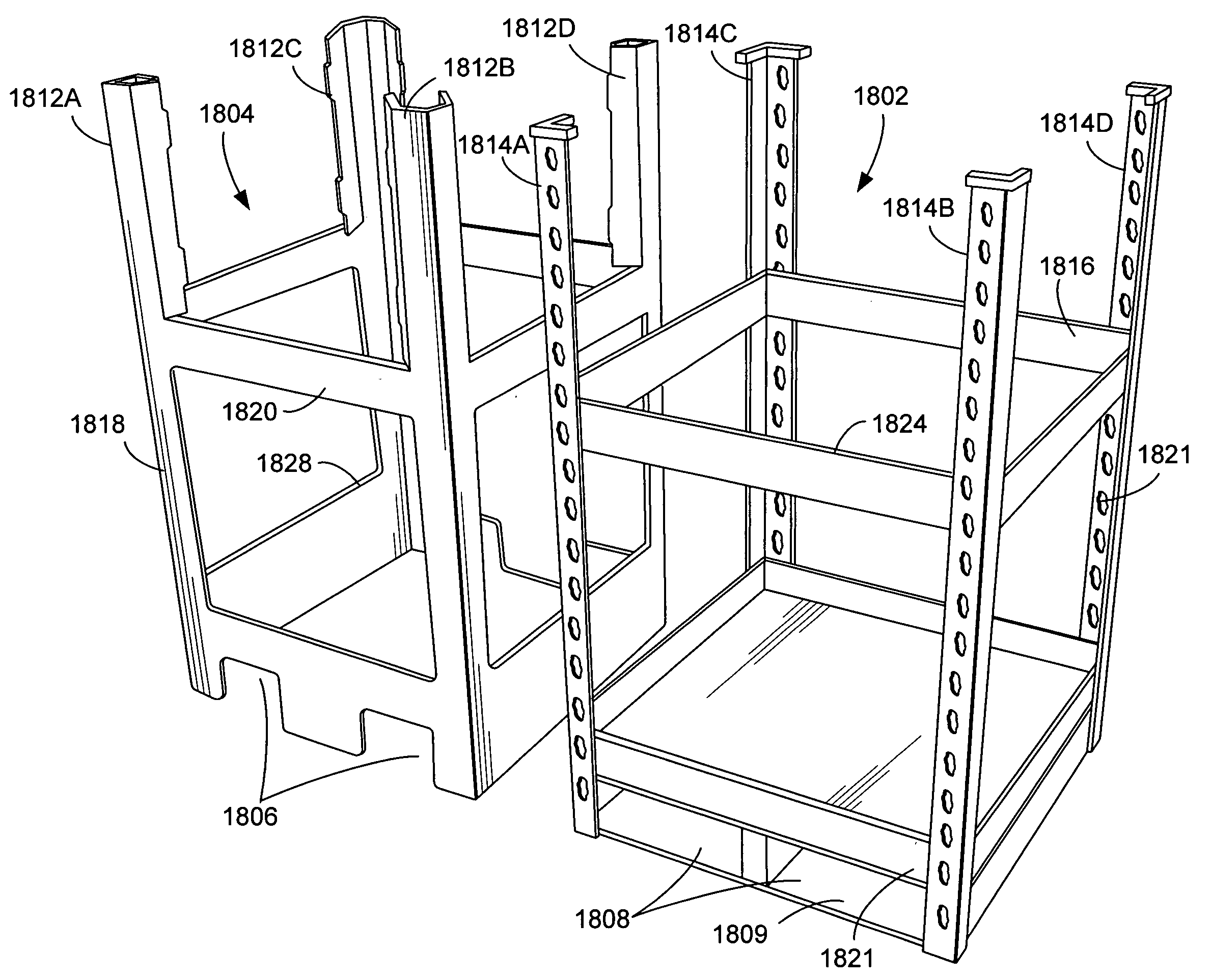
[0015] Assembly of the rack jacket is simple. It can be accomplished by simply sliding the jacket directly over an assembled rack. Die cut tabs fold over the corner posts securing the unit to the rack without need for any additional mechanical devices. Alternatively, the jacket can be assembled by wrapping it around the jacket, and thereafter securing it using tabs or external devices such as staples. Also, the bottom sections can be die cut to provide forklift and pallet jack access. This makes the loaded display easy to move while at the same time hiding the pallet itself.

Problems solved by technology

There are several problems associated with the aforementioned procedures.
Unloading and loading the corrugated boxes is a labor-intensive procedure, often resulting in damage to the products and / or the corrugated boxes.
It is also common for the products to be damaged when the corrugated boxes (which are typically stacked during storage and transportation) collapse.
Another problem with these procedures is that the corrugated boxes are not generally reusable, and must be broken down and disposed of by the retail outlets.
Alternative wood racking systems, such as those employed in nurseries, do not solve this problem.
These racking systems are also difficult to transport, require labor intensive procedures to unload transported products and display them at a retail level, and cannot be broken down easily at the retail outlet.
These devices are also typically held together with nails, which further complicate their disassembly and storage, and make any return to the manufacturer generally unprofitable.
However, the appearance of the rack systems may be unsuitable for some applications.
Further, since the rack system is designed to be easily broken down and used for a wide variety of applications, such rack systems typically do not include provisions for making an attractive retail-level display.

Method used


Image

  • Shelf assembly display jacket
  • Shelf assembly display jacket
  • Shelf assembly display jacket

Examples


Embodiment Construction

[0053] In the following description of the preferred embodiment, reference is made to the accompanying drawings which form a part hereof, and in which is shown by way of illustration a specific embodiment in which the invention may be practiced. It is understood that other embodiments may be utilized and structural changes may be made without departing from the scope of the present invention.

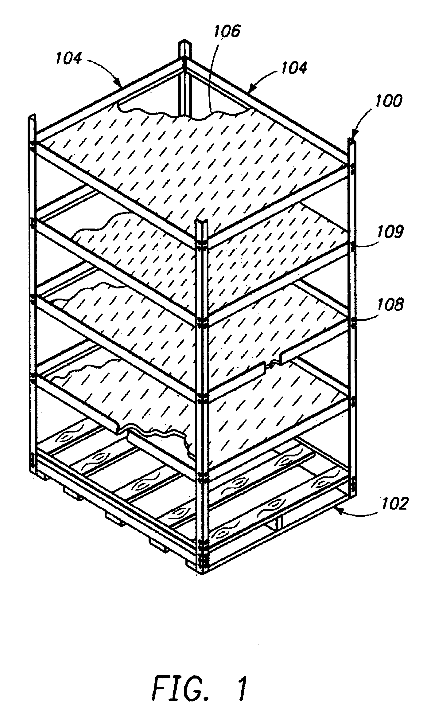
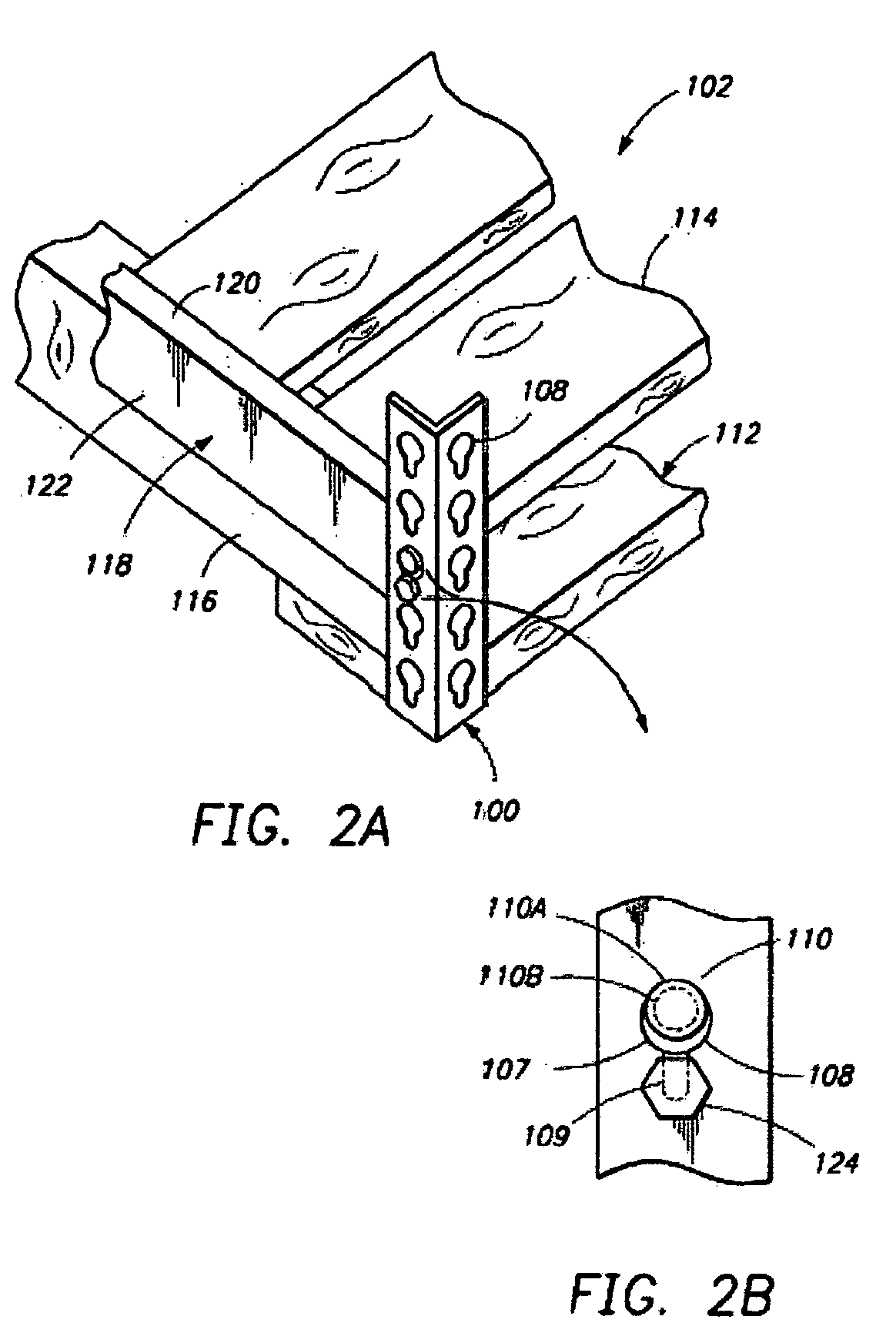
[0054]FIG. 1 presents a perspective view of one embodiment of the present invention. The invention comprises a plurality of vertical support members 100 (which may be “corner posts” having an “L” shaped cross section), which are arranged so as to accept a pallet 102 therebetween. In one embodiment, the pallet 102 is a common two-way wood pallet, which accepts forklift tongues in slots on the front and rear of the pallet 102. In an alternative embodiment, a four-way pallet may be used. The four-way pallet comprises additional slots on opposite sides of the pallet to accept forklift tongues, thus...


PUM

PropertyMeasurementUnit
Surfaceaaaaaaaaaa
Perimeteraaaaaaaaaa

Abstract

A rack jacket is disclosed. The rack jacket comprises a support member portion for covering an external surface of at least one of a plurality of support members, and a cross brace portion, for covering an external surface of at least one cross brace disposed between at least two of the vertical support member. The rack jacket is sized and shaped to conform to an exterior surface of the rack.

Description

CROSS-REFERENCE TO RELATED APPLICATIONS [0001] This application claims benefit of U.S. Provisional Patent Application Ser. No. 60 / 519,404, for “SHELF ASSEMBLY DISPLAY JACKET,” by David J. Czerwinski, filed Nov. 12, 2003. [0002] This application is also related to the following U.S. Patent Applications, each of which applications are hereby incorporated by reference herein: [0003] U.S. patent application Ser. No. 10 / 388,860, filed Mar. 14, 2003, for “MODULAR LOW COST PALLET AND SHELF ASSEMBLY,” by Jeffrey Salmanson and Jon R. Dickey, which is a continuation of U.S. patent application Ser. No. 09 / 829,589, filed Apr. 9, 2001, for “MODULAR LOW COST PALLET AND SHELF ASSEMBLY,” by Jeffrey Salmanson and Jon R. Dickey, now U.S. Pat. No. 6,609,466, issued Aug. 26, 2003, which is a continuation of U.S. patent application Ser. No. 09 / 358,285, filed Jul. 21, 1999, for “MODULAR LOW COST PALLET AND SHELF ASSEMBLY,” by Jeffrey Salmanson and Jon R. Dickey, now issued as U.S. Pat. No. 6,244,194, whi...

Claims


Application Information

Patent Timeline
IPC IPC(8): A47B47/00A47F5/10
CPCA47B47/0083A47F5/112A47F5/10A47B97/00
Inventor CZERWINSKI, DAVID J.
Owner E Z SHIPPER RACKS
Learn More