Method for manufacturing a light guide plate having light manipulating microstructures

Inactive Publication Date: 2005-05-26
HON HAI PRECISION IND CO LTD
View PDF3 Cites 17 Cited by
  • Summary
  • Abstract
  • Description
  • Claims
  • Application Information

AI Technical Summary

Benefits of technology

[0010] An object of the present invention is to provide a method for manufacturin

Problems solved by technology

However, in this method, the smallest possible size of each microstructure is about 300 microns, and the precision and variability of the shapes of microstructures are insufficient.
However, in this method, it is difficult to fabricate light guide plates having precise microstructures, because of the limitation of the precision of the machining tool of the stamper and because of wearing of the machining tool.
If the machining precision is unsatisfa

Method used


Image

  • Method for manufacturing a light guide plate having light manipulating microstructures
  • Method for manufacturing a light guide plate having light manipulating microstructures
  • Method for manufacturing a light guide plate having light manipulating microstructures

Examples


Embodiment Construction

[0017] Reference now will be made to the drawings to describe the present invention in detail.

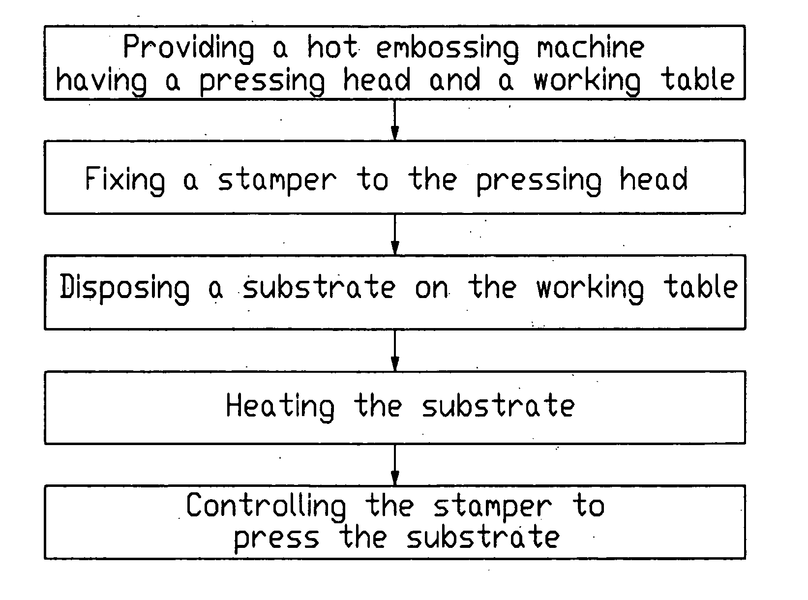
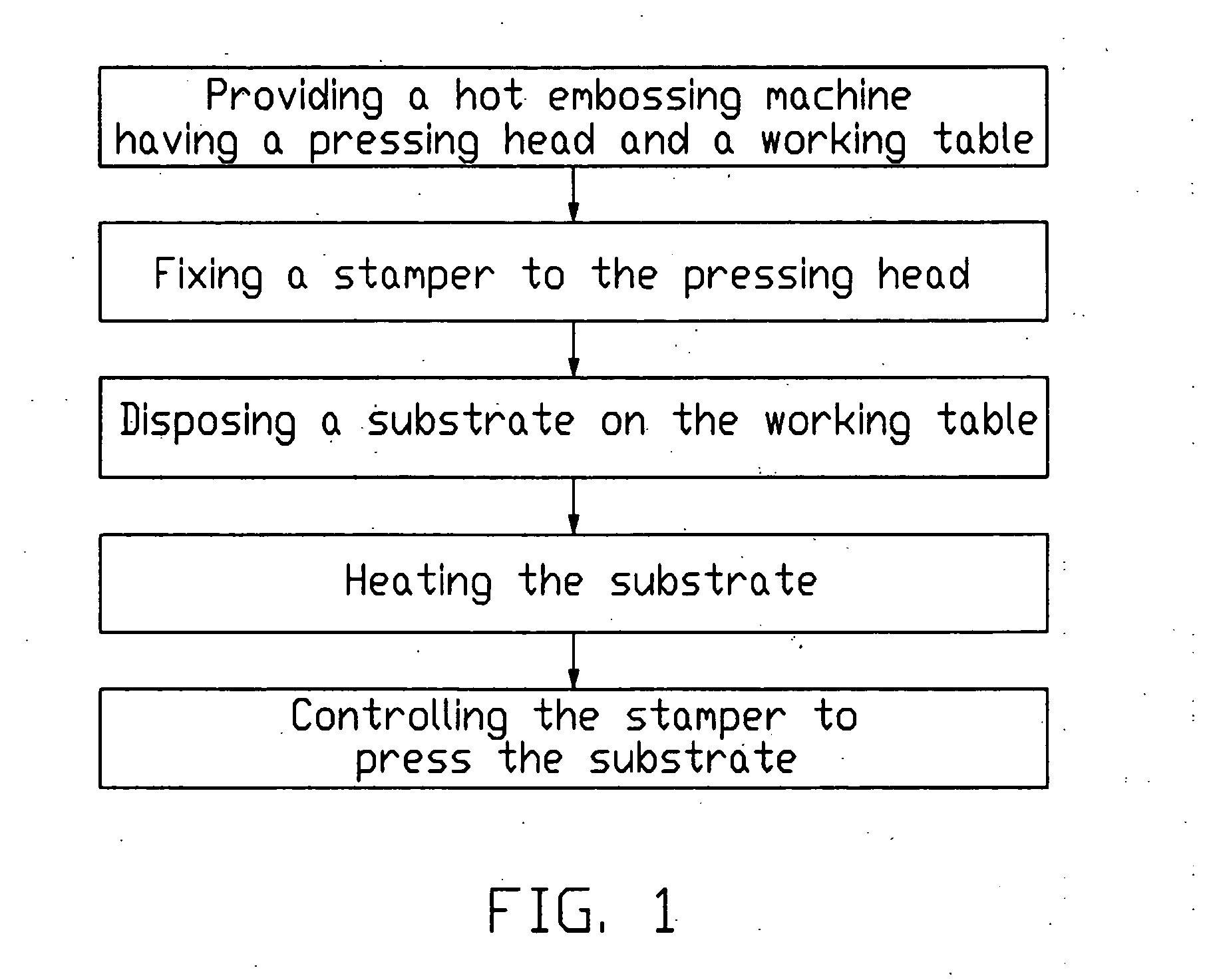
[0018] Referring to FIG. 1, a flow chart of a method for manufacturing a light guide plate having light spreading microstructures according to the present invention is shown. The steps involved in the manufacturing method are: providing a hot embossing machine having a pressing head and a working table; fixing a stamper to the pressing head; disposing a substrate on the working table; heating the substrate; and controlling the stamper to the press the substrate.

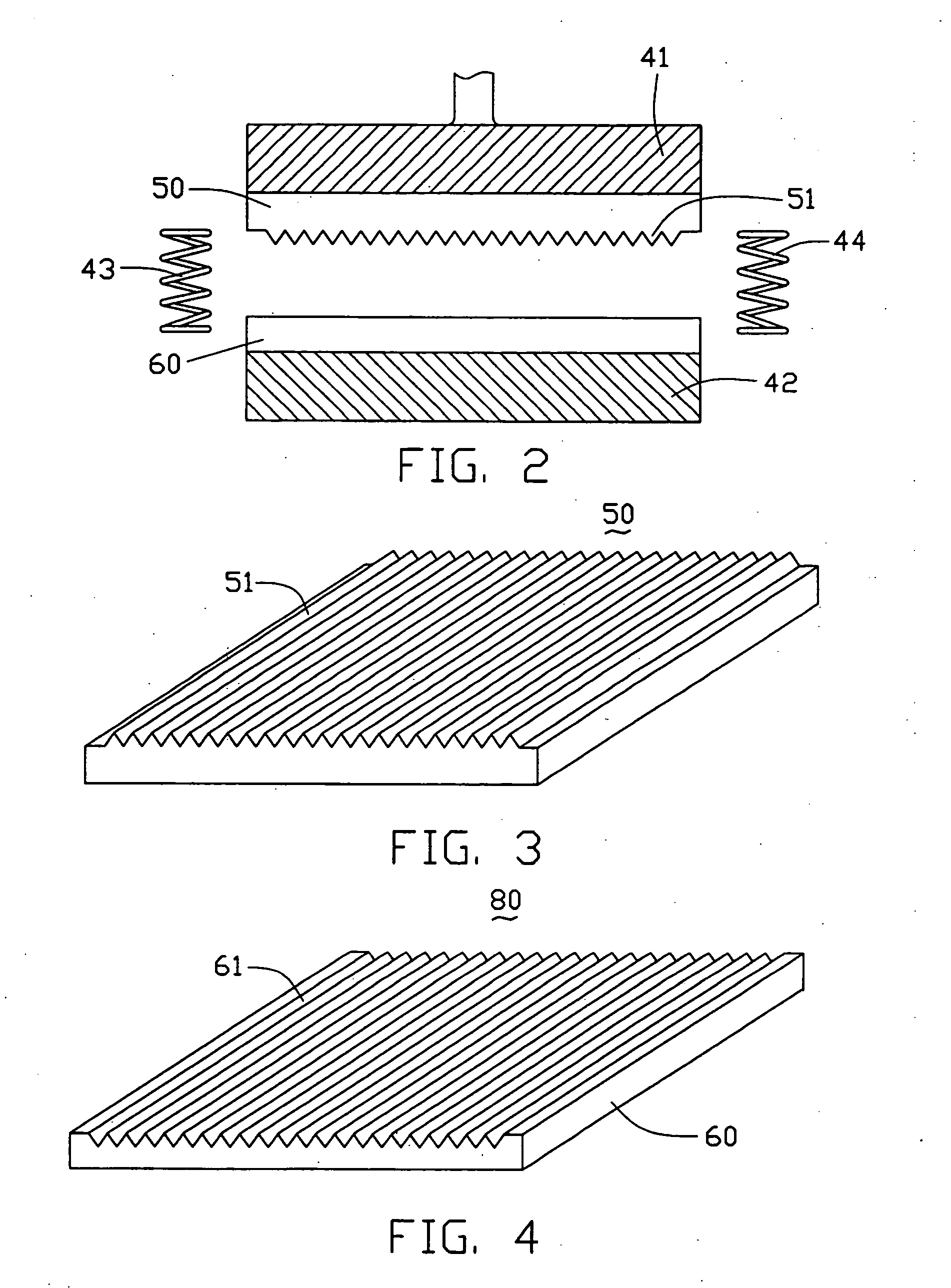
[0019] Referring to FIG. 2, in the initial step, a hot embossing machine (not labeled) is provided. The hot embossing machine includes a pressing head 41, a working table 42, and a pair of heating apparatuses 43 and 44 disposed around the working table 42. The working table 42 and the heating apparatus 43 and 44 cooperatively apply heat to a light guide plate substrate 60 attached to the working table 42. The pressing head 41 can m...


PUM

PropertyMeasurementUnit
Lengthaaaaaaaaaa
Temperatureaaaaaaaaaa
Pressureaaaaaaaaaa

Abstract

A method for manufacturing a light guide plate includes the steps of: providing a hot embossing machine having a pressing head and a working table; providing and fixing a stamper to the pressing head, the stamper having microstructures in a surface thereof facing the working table; disposing a substrate on the working table; heating the substrate; and pressing the stamper onto the substrate to form light manipulating microstructures at a surface of the substrate. In this process, the substrate is heated to a state just short of fusing. Therefore the pressure applied by the stamper need not be very large. This allows greater control of the precision of stamping by the stamper. The method is particularly efficacious for fabricating large sized light guide plates, such as those used in LCD TVs and the like.

Description

BACKGROUND OF THE INVENTION [0001] 1. Field of the Invention [0002] The present invention relates to a method for fabricating a light guide plate used for a liquid crystal display (LCD), and more particularly to a method for manufacturing a light guide plate having light spreading microstructures. [0003] 2. Description of the Prior Art [0004] A typical LCD device comprises a liquid crystal display panel, and a backlight system mounted under the liquid crystal display panel for supplying light beams thereto. The backlight system mainly comprises a light source and a light guide plate. The light guide plate is made of a transparent acrylic plastic, and is used for guiding light beams received from the light source to uniformly illuminate the liquid crystal display panel. [0005] The light source emits light beams into the light guide plate, and at least some of the light beams are liable to be totally internally reflected within the light guide plate. In order to diffuse the light beam...

Claims


Application Information

Patent Timeline
IPC IPC(8): B29C59/02B29D11/00
CPCB29C59/022B29L2011/0075B29D11/00663B29C2059/023
Inventor CHEN, GA-LANE
Owner HON HAI PRECISION IND CO LTD
Why Eureka
Try Eureka