
Supporting spacers of a flat display device

Inactive Publication Date: 2005-05-26
SAMSUNG SDI CO LTD
View PDF5 Cites 7 Cited by
  • Summary
  • Abstract
  • Description
  • Claims
  • Application Information

AI Technical Summary

Benefits of technology

[0018] The present invention provides a spacer supporting structure that can maintain a gap between two panels of a flat display device and can minimize an alignment error of spacers during a high temperature process and a method of supporting spacers.

Problems solved by technology

In this case, components between the two panels can be damaged, especially when a gap between the front panel and the rear panel becomes uneven due to a deformation, in which case the electron emission and the control of the emission may be impossible.
However, mounting the numerous cross-shaped spacers on the rear panel of a large flat display device can take a long time.
Also, the rear panel can be contaminated by the adhesive used to attach the cross-shaped spacers, and the contamination of the rear panel can degrade the image quality of the flat display device.
The bar-shaped spacer is easily manufactured and requires a short installation time.
However, the bar-shaped spacer is not well suited to a high temperature sealing process since it only has support along one dimension.
If so, the bar-shaped spacer may not remain in the correct position, resulting in misalignment of the bar-shaped spacers, cathodes, and anodes.
When there is a misalignment of a bar-shaped spacer, the spacer may cover a pixel or interact with an electron beam between anodes and cathodes, which can cause a bright spot due to an electron charging effect, or can cause arcing due to a partial distortion of an electric field.
However, since the spacers are fixed only at one end, the alignment can easily be distorted by the flow of an inert gas injected between the two panels to prevent an oxidation of an electron emitter at a high temperature.

Method used


Image

  • Supporting spacers of a flat display device
  • Supporting spacers of a flat display device
  • Supporting spacers of a flat display device

Examples


Embodiment Construction

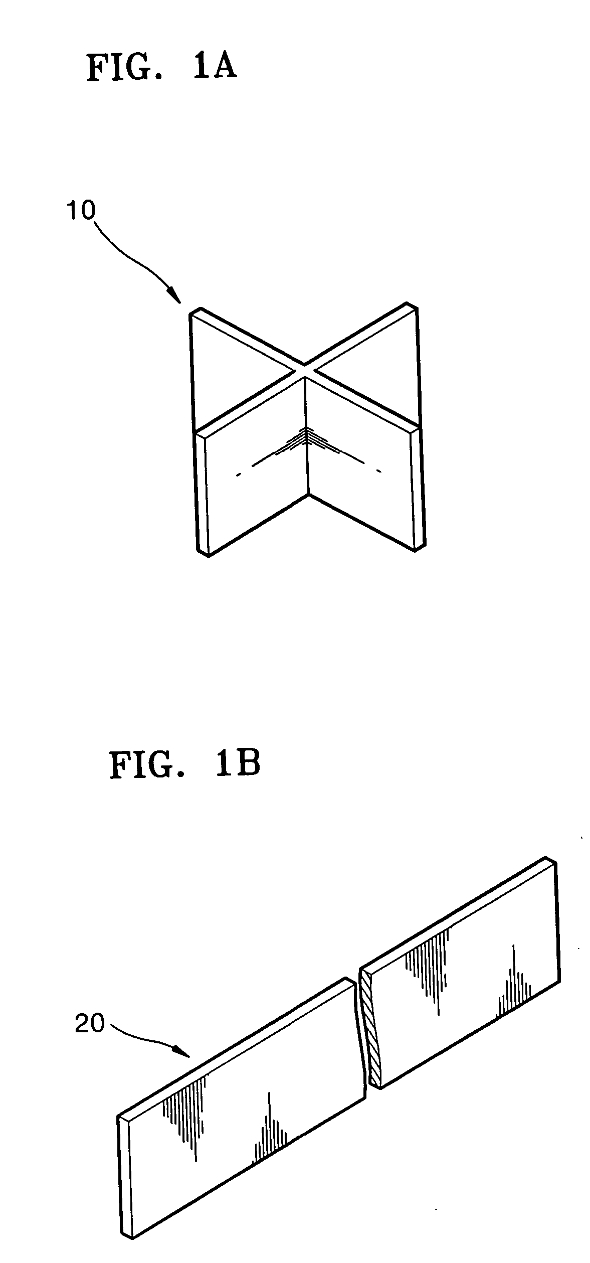
[0062] Referring to FIGS. 1A and 1B, a cross-shaped spacer 10 and a bar-shaped spacer 20 are widely used in flat display devices.

[0063] The cross-shaped spacer 10 is manufactured piece by piece by etching or injection molding. In order to maintain the gap between the front panel and the rear panel, the cross-shaped spacer 10 is required to dispose about one˜five pieces per square centimeter. Generally, the cross-shaped spacer 10 is mounted by an adhesive on the rear panel. More specifically, a small amount of the adhesive is coated on the rear panel or on the spacer 10 and then the spacer 10 is attached to the rear panel.

[0064] The cross-shaped spacer 10 can be attached to a correct location on the rear panel since it is mounted piece by piece, and almost no deformation is observed after sealing at a high temperature during the manufacturing process of flat display devices. However, mounting the numerous cross-shaped spacers 10 on the rear panel of a large flat display device can ...


PUM


Abstract

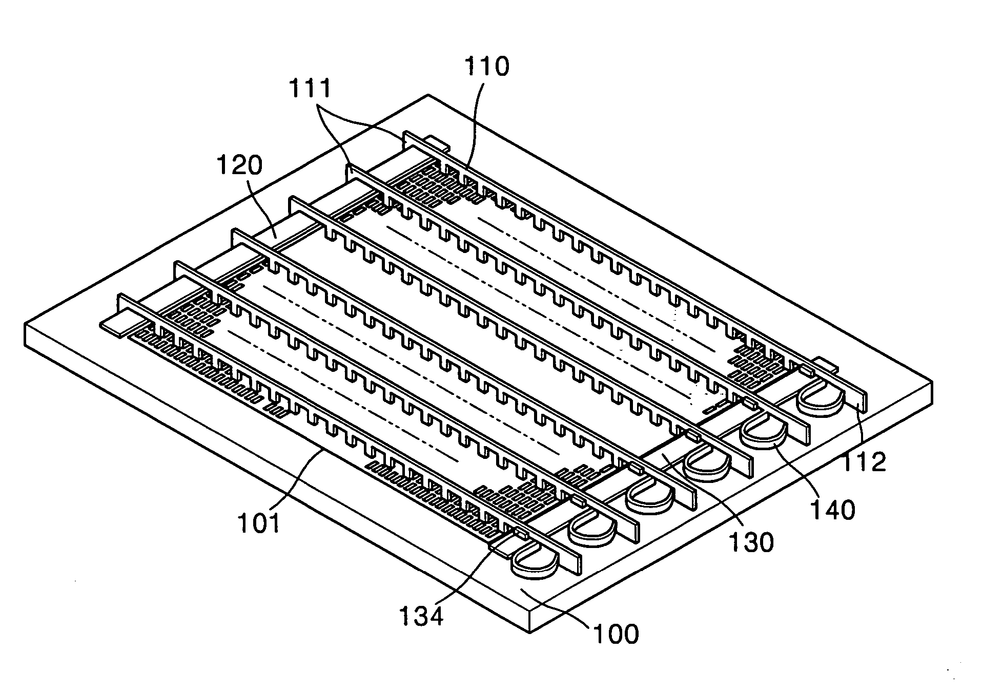
A spacer supporting structure includes: a plurality of bar-shaped spacers adapted to maintain a gap between two panels; a first supporting member adapted to fix an end part of the spacer, the first supporting member being arranged on an edge of one of the two panels; a second supporting member arranged on another edge of the one of the two panels; and a plurality of elastic members arranged on the second supporting member, the plurality of elastic members adapted to apply a tensile force to the respective spacers by being coupled to the second ends of the spacers.

Description

CLAIM OF PRIORITY [0001] This application makes reference to, incorporates the same herein, and claims all benefits accruing under 35 U.S.C. §119 from an application for SPACER SUPPORTING STRUCTURE FOR FLAT DISPLAY DEVICE AND METHOD OF SUPPORTING SPACERS earlier filed in the Korean Intellectual Property Office on 25 Nov. 2003 and there duly assigned Serial No. 2003-84181. BACKGROUND OF THE INVENTION [0002] 1. Field of the Invention [0003] The present invention relates to a flat display device, and more particularly, to a spacer supporting structure for a flat display device adapted to maintain a gap between two panels of the flat display device and a method of supporting spacers. [0004] 2. Description of the Related Art [0005] Typical important applications of display devices include monitors for personal computers and television screens. The display devices include Cathode Ray Tubes (CRTs), which use the emission of heated electrons at a high speed, and flat display devices, which ...

Claims


Application Information

Patent Timeline
IPC IPC(8): H01J1/30H01J9/24H01J9/18H01J29/02H01J29/86H01J29/87H01J31/12
CPCH01J9/242H01J29/864H01J2329/8665H01J2329/8625H01J2329/863H01J31/123H01J1/30
Inventor SONG, BYONG-GWONSHIN, MOON-JIN
Owner SAMSUNG SDI CO LTD
Learn More