Optical transmission and receiving device for implementing passive alignment of components and method for passively aligning components

Active Publication Date: 2013-05-23
SAMJIN C&I CO LTD
View PDF26 Cites 28 Cited by
  • Summary
  • Abstract
  • Description
  • Claims
  • Application Information

AI Technical Summary

Benefits of technology

The present invention simplifies the optical alignment process for multiple channels, reduces the number of parts used, and improves efficiency and convenience. It also allows for the mass production of bi-directional optical devices that are simple in structure and assembly method, and lay the foundation for greater advancements in data communication speeds with low costs.

Problems solved by technology

In conventional methods of signal transmission based on fiber optics, however, the optical device for coupling the light-emitting elements with the optical fiber or for coupling the light emitted from the optical fiber with the light-receiving elements is not only very expensive but also quite difficult to use in performing optical alignment.
This method of active optical alignment, in which the light-emitting element or light-receiving element is driven directly and the degree of alignment with the optical fiber is sensed in real time to yield the optimum degree of alignment, requires a time-consuming manufacture process and expensive assembly apparatus.

Method used


Image

  • Optical transmission and receiving device for implementing passive alignment of components and method for passively aligning components
  • Optical transmission and receiving device for implementing passive alignment of components and method for passively aligning components
  • Optical transmission and receiving device for implementing passive alignment of components and method for passively aligning components

Examples


Embodiment Construction

[0108]FIG. 11 illustrates a method of aligning parts with respect to holes in the substrate without using an alignment reference part, according to another embodiment of the present invention.

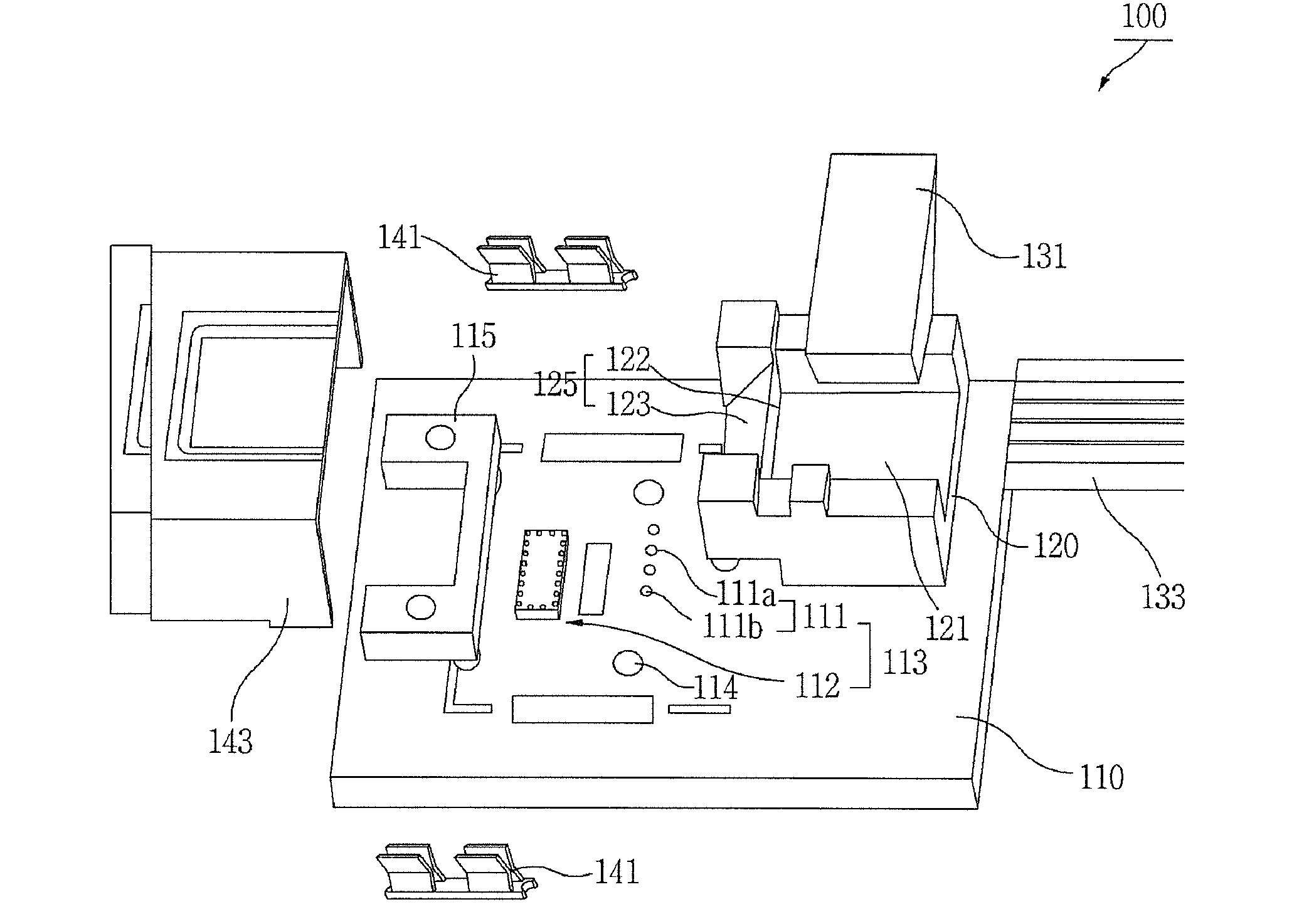
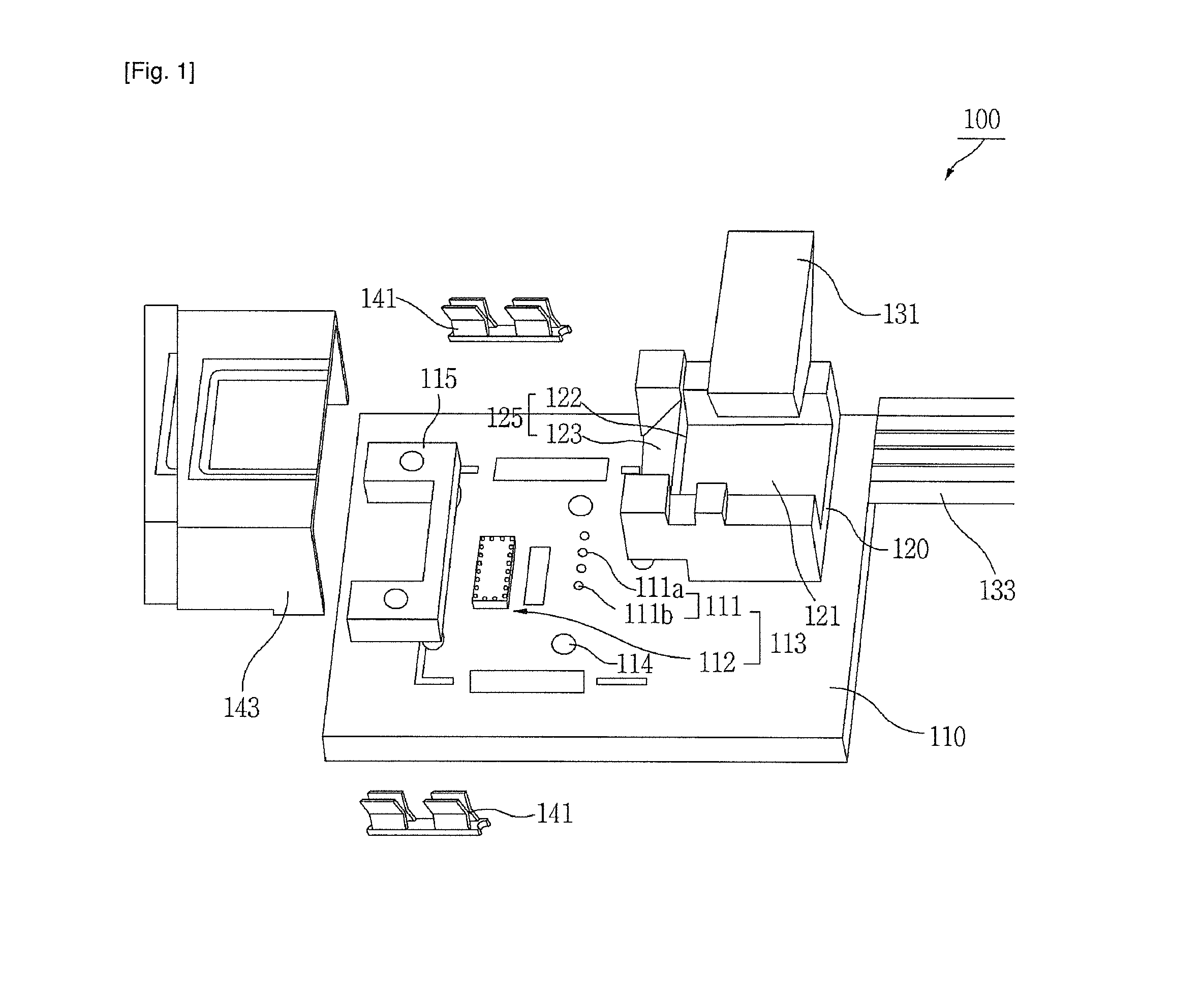
[0109]Referring to FIG. 11, a method of aligning parts according to another embodiment includes a first step of aligning the light-emitting elements 111a and the light-receiving elements 111b in particular intervals on the substrate 110 with the holes 114 of the substrate as alignment points, a second step of aligning the lens-optical fiber connection part 120 with the holes 114 of the substrate as alignment points, and a third step of aligning the optical fiber 133 with the optical fiber connector 121 to complete the optical alignment.

[0110]With this method, the substrate holes 114 are used as reference for the optical alignment, so that the alignment reference part 115 for optical alignment can be removed, and the number of parts can be reduced.

[0111]The major component parts included in the ...


PUM

PropertyMeasurementUnit
Transparencyaaaaaaaaaa
Refractive indexaaaaaaaaaa
Optical propertiesaaaaaaaaaa

Abstract

An optical device for implementing passive alignment of parts and a method therefore, more particularly an optical device and a method therefore that utilize an alignment reference part 115 arranged on the substrate 110 to passively align an optical element part 111 with a lens-optical fiber connection part 120. For the passive alignment of parts, connection pillars 115b of an alignment reference part 115 are coupled to substrate holes 114, one or more light-emitting elements 111a and one or more light-receiving elements 111b are aligned in a row in a particular interval with respect to alignment holes 115a arranged opposite each other in the alignment reference part 115, a lens-optical fiber connection part 120 is aligned with respect to the alignment holes 115a, and an optical fiber 133 is aligned with the optical alignment point at a surface 122b of a prism forming a portion of the lens-optical fiber connection part 120. In addition, the optical fiber 133 is secured with an optical fiber pin 131, after which a metal case 143 is covered and coupled with a case securing pin 141. The optical device for implementing passive alignment of parts provides the advantages of simplifying the passive optical alignment for multiple channels, so as to minimize alignment error, and of reducing and simplifying the structure of the optical modules and minimizing the number of parts used, so as to lower the costs of the optical modules.

Description

TECHNICAL FIELD[0001]The present invention relates to an optical device for implementing passive alignment of parts and a method therefore, more particularly to an optical device and a method therefore that utilize an alignment reference part arranged on the substrate to passively align an optical element part with a lens-optical fiber connection part.BACKGROUND ART[0002]Methods of signal transmission based on fiber optics, which are already widely used in long-distance communication, provide the advantages of broad bands and immunity to electromagnetic interference (EMI), and are thus being applied to high-capacity digital media transmissions, such as for high-definition digital video display devices, which require high-speed, high-density data transmissions.[0003]In conventional methods of signal transmission based on fiber optics, however, the optical device for coupling the light-emitting elements with the optical fiber or for coupling the light emitted from the optical fiber wi...

Claims


Application Information

Patent Timeline
IPC IPC(8): G02B6/26G02B6/34G02B6/32
CPCG02B6/4214G02B6/423G02B6/4243G02B6/4244G02B6/4245Y10T29/49895G02B6/4277G02B6/26G02B6/32G02B6/34G02B6/4249G02B6/4206G02B6/4231G02B6/4239G02B6/424G02B6/425G02B6/4257
Inventor SON, YUNG SUNGLEE, SANG-SHINLEE, HAK-SOONPARK, JUN-YOUNG
Owner SAMJIN C&I CO LTD
Why Eureka
Try Eureka