Beamforming Architecture For Multi-Beam Phased Array Antennas

a phased array antenna and beamforming technology, applied in the direction of antenna support/mounting, resonance antenna, radiating element structural form, etc., can solve the problems of reducing the reliability of the antenna, reducing and dividing layers of the phased array antenna, etc., to reduce the number of separable interconnections, reduce the number of beamforming, combining and dividing layers

Active Publication Date: 2005-05-26
THE BOEING CO
View PDF17 Cites 52 Cited by
  • Summary
  • Abstract
  • Description
  • Claims
  • Application Information

AI Technical Summary

Benefits of technology

[0010] The embodiments of the present invention provide several advantages. One such advantage that is provided by multiple embodiments of the present invention is the provision of subarray beamformer configured such that the number of beamforming, combining, and dividing layers within a phased array antenna is reduced. The reduced number of modules and layers reduces the number of separable interconnections within a phased array antenna.
[0011] Another advantage that is provided by multiple embodiments of the present invention is the provision of simplifying the layers within a subarray beamformer, which further reduces the number of separable interconnections within a phased array antenna.
[0012] The above stated advantages in reducing the number of interconnections, minimize integration time and manufacturing costs, and improve reliability of a phased array antenna.

Problems solved by technology

Integration of these components can be time consuming and interconnections contained therein can degrade reliability of an antenna.
Also, due to limited space on a satellite, there is a limited amount of area on the non-signal transmission side of the radiating element of the antenna for the above stated circuitry and structures.
The interconnections can negatively affect reliability and correspond to an increase in associated components.
The interconnections and the associated costs involved therein increase costs in an antenna and increase componentry integration time.
The physical size of the antenna also limits the mounting locations for the antenna.

Method used


Image

  • Beamforming Architecture For Multi-Beam Phased Array Antennas
  • Beamforming Architecture For Multi-Beam Phased Array Antennas
  • Beamforming Architecture For Multi-Beam Phased Array Antennas

Examples


Embodiment Construction

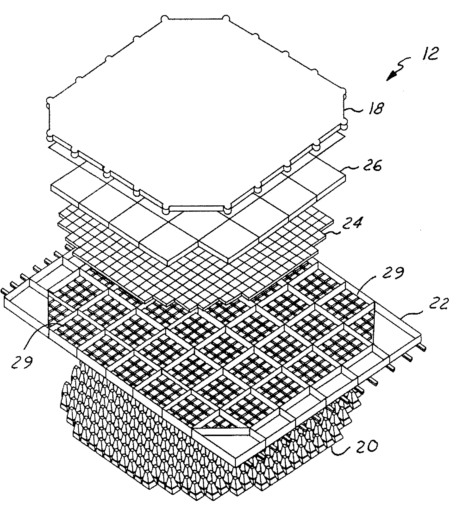
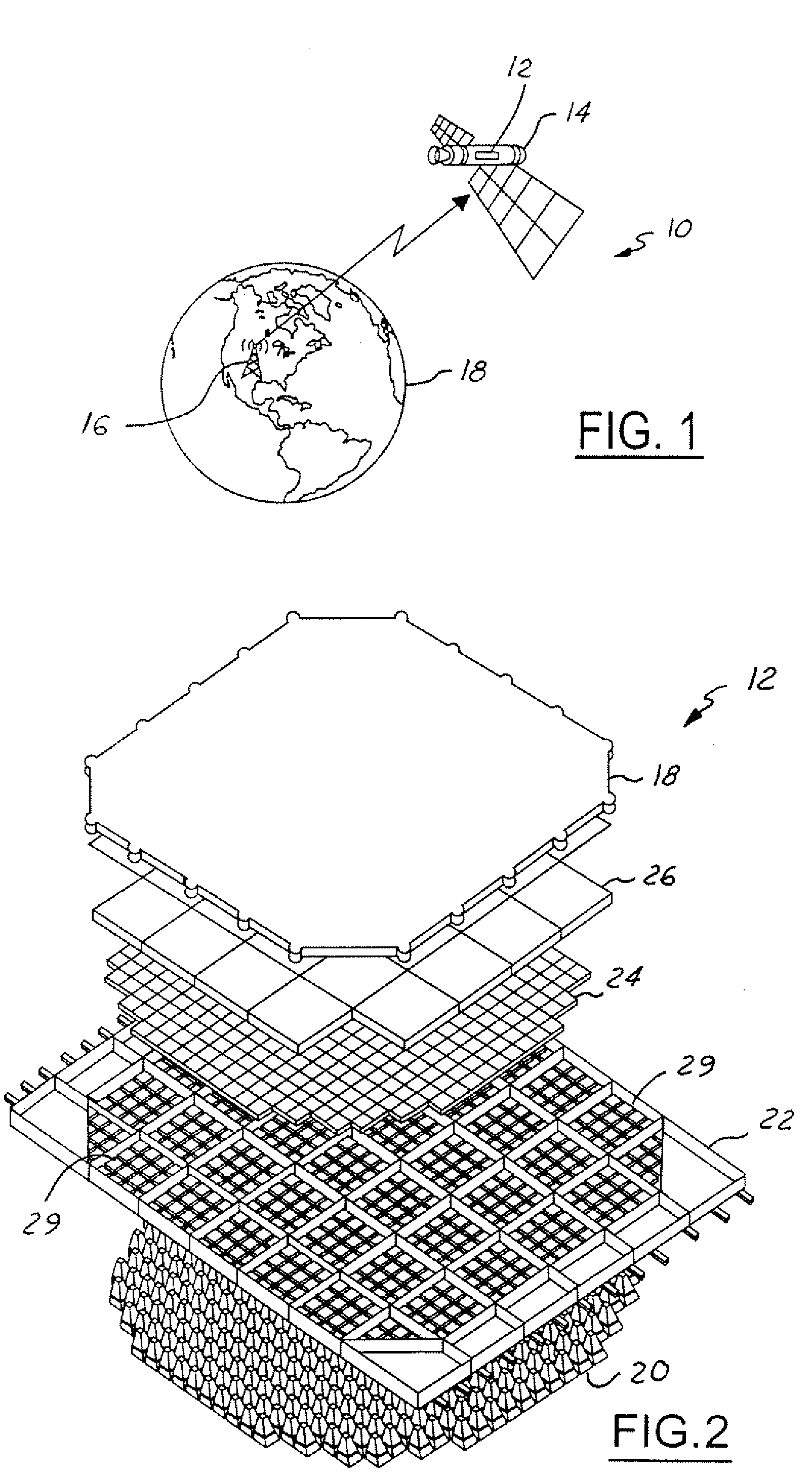
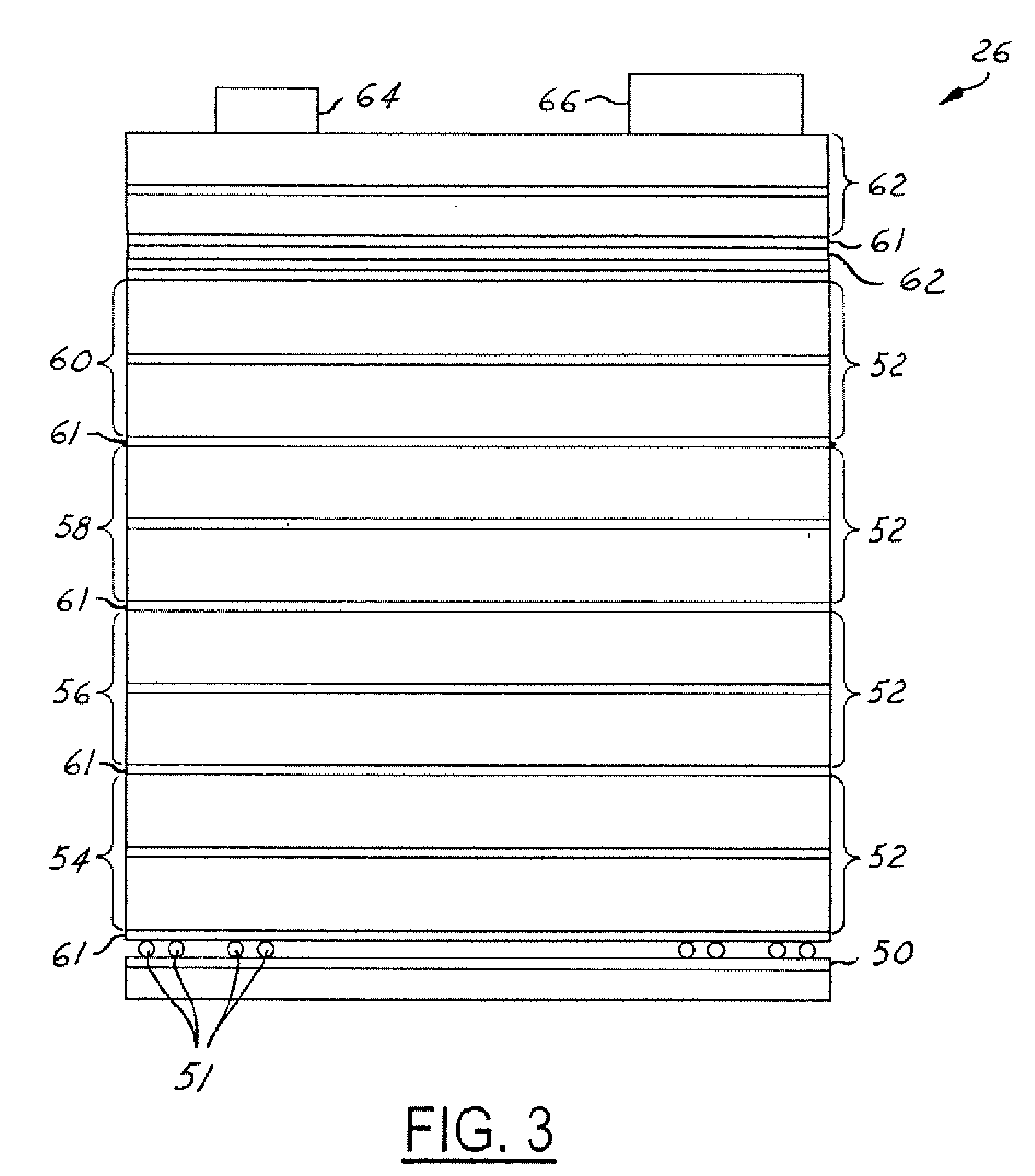
[0023] In the following figures, the same reference numerals will be used to refer to the same components. While the present invention is described with respect to an assembly for combining communication signals within a beamforming architecture of a multi phased array antenna, the present invention may be adapted for use in various applications known in the art. The present invention may be applied in military and civilian applications. The present invention may be applied to aerospace systems, communication systems, spacecraft systems, telecommunication systems, intelligent transportation systems, global positioning systems, and other systems known in the art. Although the present invention is described primarily with respect to a multi-beam phased array antenna, the present invention may be applied to other antennas known in the art.

[0024] In the following description, various operating parameters and components are described for one constructed embodiment. These specific parame...


PUM


Abstract

A first subarray beamformer for a multi-beam phased array antenna (12) used in a receiving mode includes multiple phased array antenna beamforming layers. The beamforming layers include a first beamforming layer (90) that may have a first series of combiners in a first orientation. The first series of combiners combine a first set of signals to form a second set of signals. A second beamforming layer (110) may have a second series of combiners in a second orientation that are coupled to and oppose the first series of combiners. The second series of combiners combine the second set of signals to form a first combined signal. A second subarray beamformer for a multi-beam phased array antenna used in a transmitting mode that has a similar configuration as that of the first subarray beamformer, but includes dividers rather than combiners.

Description

BACKGROUND OF INVENTION [0001] The present invention is related generally to satellite communication systems. More particularly, the present invention is related to an assembly for combining communication signals within a beamforming architecture of a multi-beam phased array antenna. [0002] Multi-beam antennas are used in a variety of communication applications, such as on satellites. Current multi-beam antennas are divided into two classes, the fixed spot beam type and the multi-beam phased array type. The fixed spot beam type antennas require additional design investment, such as in componentry and system control, to provide beam pointing and shape altering capability. The multi-beam phased array type antennas can be electronically reconfigured without such design investment, but are commonly formed in a “brick” type architecture. The brick architecture has significant height and a substantial amount of components. [0003] Phase array antennas typically include multiple radiating e...

Claims


Application Information

Patent Timeline
Patent Type & Authority Applications(United States)
IPC IPC(8): H01Q1/24H01Q25/00
CPCH01Q25/00H01Q1/246
Inventor LONDRE, DALE A.
Owner THE BOEING CO
Why Eureka
Try Eureka