Driving circuit for an organic electroluminescence display

a driving circuit and electroluminescence technology, applied in the direction of instruments, static indicating devices, etc., can solve the problems of degrading brightness uniformity, different current flowing out of different transistor groups, etc., and achieve the effect of reducing the variation of driving current flowing

Inactive Publication Date: 2005-05-26
AIMS
View PDF3 Cites 0 Cited by
  • Summary
  • Abstract
  • Description
  • Claims
  • Application Information

AI Technical Summary

Benefits of technology

[0011] The present invention provides a driving circuit for an organic EL display that has a unique arrangement of pixels and driving transistors in the driver IC to reduce variations in the driving current flowing through the adjacent pixels of the organic EL display. According to the present invention, I(n), a driving current of the n-th pixel, is determined not by the output current of the transistors belonging to the transistor group B(n) that is geometrically most adjacent to the n-th pixel, but by the output current of other transistor groups. IB(n) refers to current flowing out of one transistor of the transistor group B(n). In one embodiment and referring to FIG. 2 as an example, there are transistors 33, 34 forming the transistor group B(n), transistors 31, 32

Problems solved by technology

Indeed, there have always been differences between current flowing out of different transistor grou

Method used


Image

  • Driving circuit for an organic electroluminescence display
  • Driving circuit for an organic electroluminescence display
  • Driving circuit for an organic electroluminescence display

Examples


Embodiment Construction

[0019] A driving circuit of an organic electroluminescence (EL) display according to one embodiment of the present invention will be described in detail with reference to the accompanying drawings. However, the present invention is not limited to the following embodiments. It will be apparent to one of ordinary skill in the art that the present invention is applicable to driving circuits for both passive and active matrix organic electroluminescence (EL) displays.

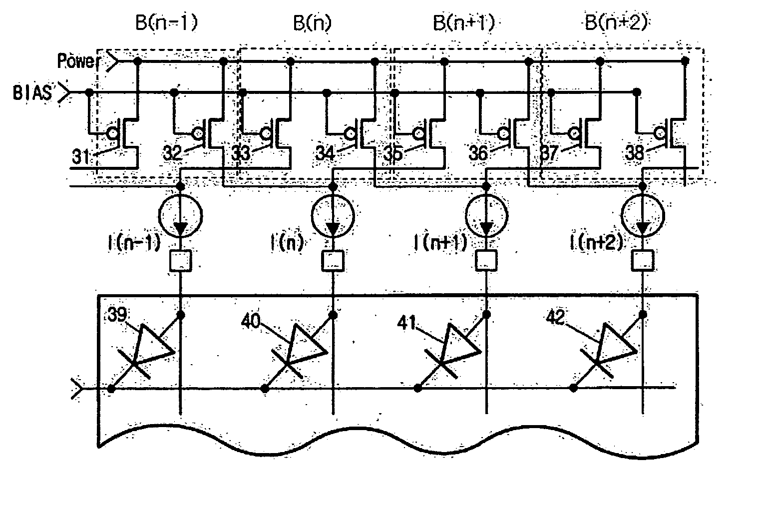
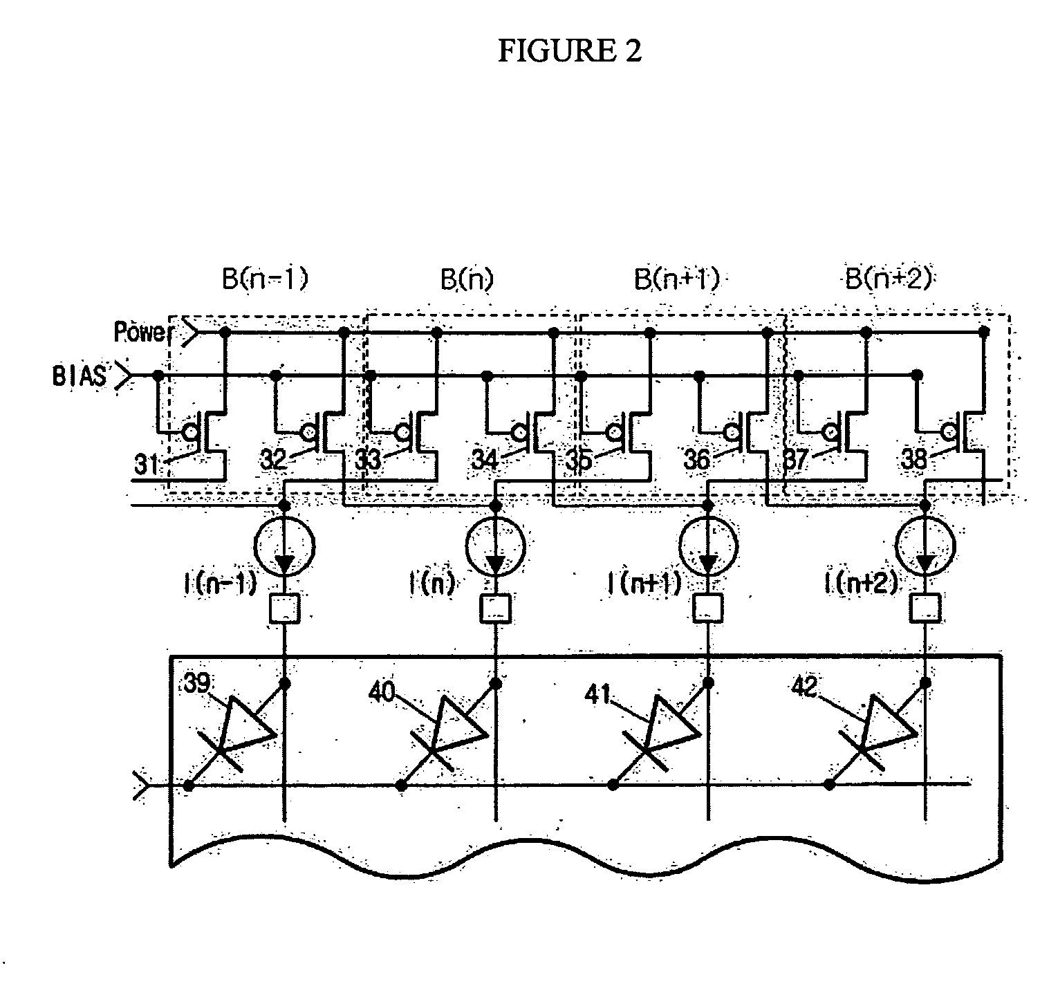
[0020]FIG. 2 is a simplified diagram of a driving circuit of an organic electroluminescence (EL) display according to one embodiment of the present invention. The organic electroluminescence (EL) display includes diodes 39, 40, 41, 42 assigned for each pixel, and the diodes 39, 40, 41, 42 operate with current flowing out of transistors 31, 32, 33, 34, 35, 36, 37, 38 assigned for each pixel.

[0021] In one embodiment, the transistors 31, 32, 33, 34, 35, 36, 37, 38 are p-channel metal-oxide semiconductor (PMOS) transistors us...


PUM


Abstract

A driving circuit of an organic electroluminescence display is configured such that the driving current I(n) flowing through an n-th pixel of the organic electroluminescence display is determined not by the current flowing out of transistors of a transistor group B(n) that are geometrically most adjacent to the n-th pixel but by the current flowing out of transistors which are geometrically most adjacent to other pixels. This configuration reduces the variation in the differences between driving current flowing through adjacent pixels, thereby improving the display quality of the organic electroluminescence display.

Description

CROSS-REFERENCE TO RELATED APPLICATION [0001] This application claims priority under 35 U.S.C. §119(a) from Republic of Korea Patent Application No. 10-2003-0082853 filed on Nov. 21, 2003. TECHNICAL FIELD [0002] The present invention relates to a driving circuit of an organic electroluminescence (EL) display, and more specifically, to a driving circuit which can improve the display quality of an organic EL display by way of reducing variations in differences between current flowing through two adjacent pixels through a unique arrangement of pixels and the transistors providing the pixels with driving current. BACKGROUND OF THE INVENTION [0003] An organic EL display, also known as an organic light-emitting diode (OLED) display, is a flat panel display which utilizes the self-luminescence phenomenon. Organic luminescent material emits light when electrons and holes therein are combined due to an electric field applied to the organic luminescent material. Since organic EL displays have...

Claims


Application Information

Patent Timeline
IPC IPC(8): G09G3/30G09G3/32
CPCG09G3/3208G09G2320/0233G09G3/3275G09G3/30
Inventor KIM, CHANG OONAHN, SUNG TAE
Owner AIMS
Why Eureka
Try Eureka