Heat radiating system and method for a mobile communication terminal

Active Publication Date: 2005-05-26
LG ELECTRONICS INC
View PDF7 Cites 112 Cited by
  • Summary
  • Abstract
  • Description
  • Claims
  • Application Information

AI Technical Summary

Benefits of technology

[0011] The thermal paste is a viscous material for transferring heat generated from the heat generating component to the shield frame and prevents heat

Problems solved by technology

When the mobile terminal (such as a cell phone) contacts a user's hand or face, the h

Method used


Image

  • Heat radiating system and method for a mobile communication terminal
  • Heat radiating system and method for a mobile communication terminal
  • Heat radiating system and method for a mobile communication terminal

Examples


Embodiment Construction

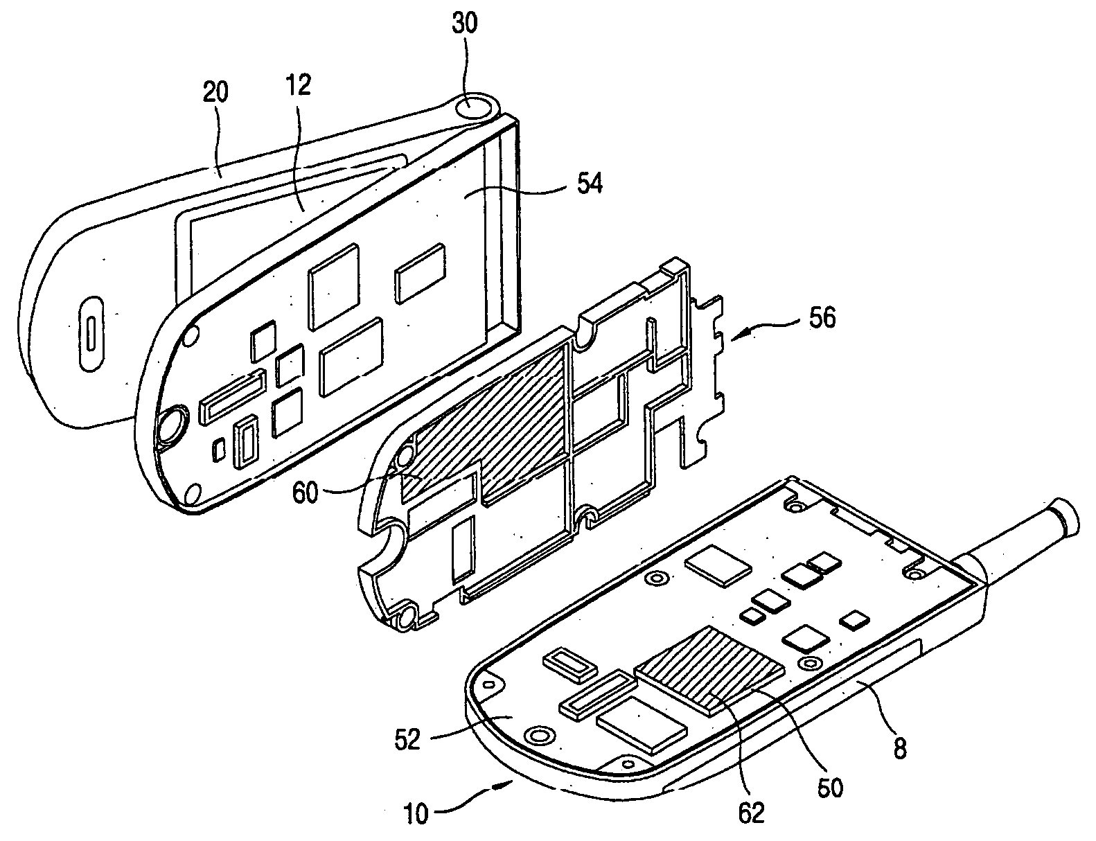
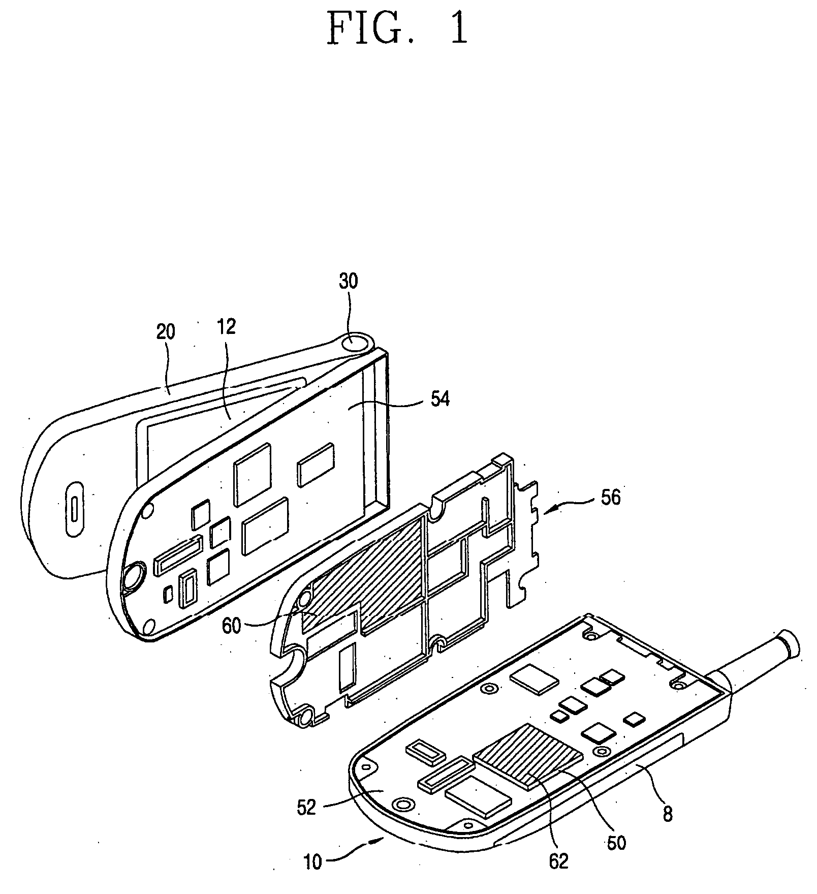
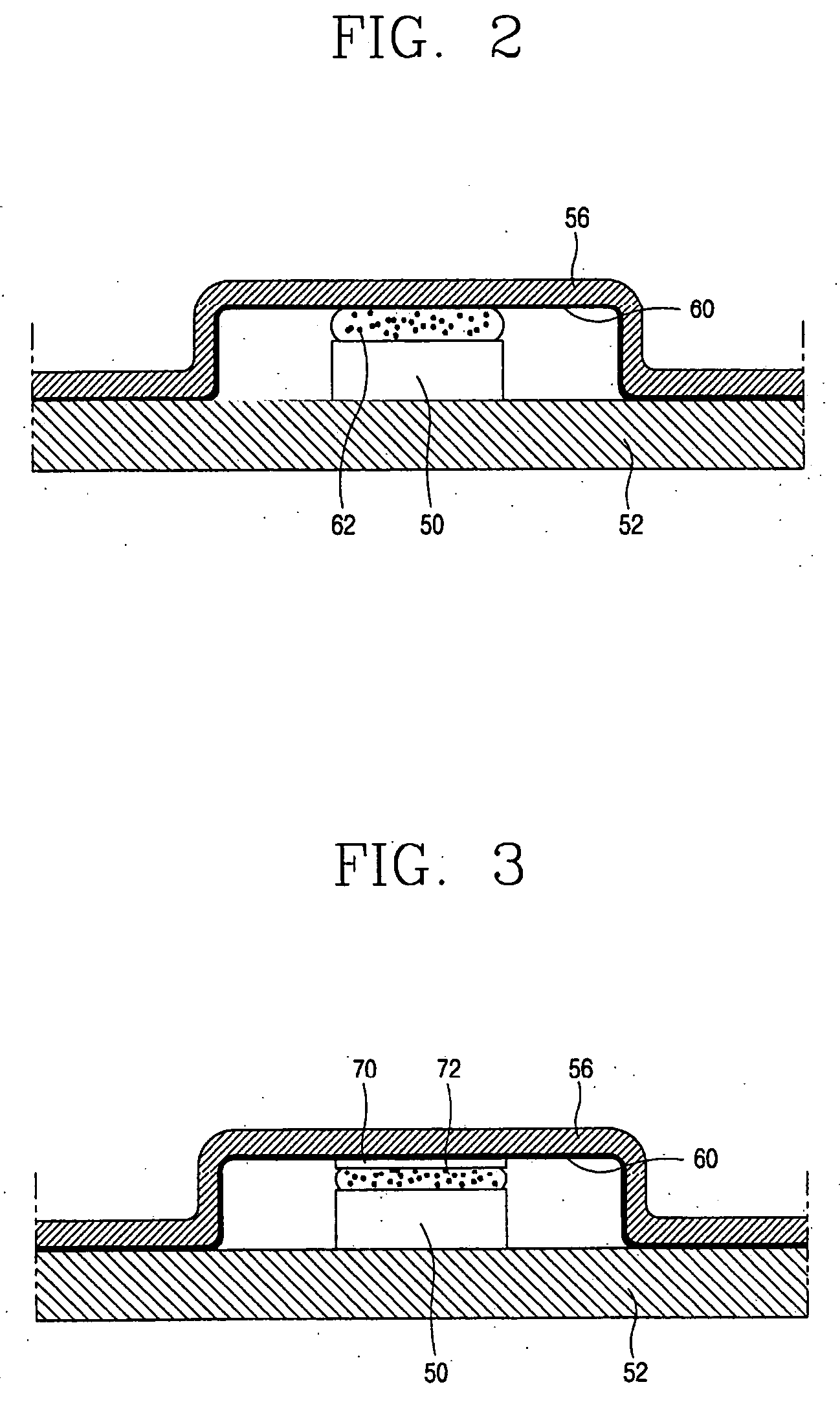
[0027] The present invention relates to a system and method for reducing heat generated by a terminal in a mobile communication system. The invention provides a heat radiating apparatus installed between the heat generating component and a shield frame for preventing electromagnetic energy generated by the electrical components reaching the main printed circuit board.

[0028] Although the invention is illustrated with respect to a mobile terminal using shield frame, it is contemplated that the invention may be utilized in other devices for reducing heat from electronic components when transmitting, receiving, or processing signals from one location to another location, for example.

[0029] The present invention provides a portable terminal having a heat radiating apparatus capable of effectively radiating heat generated from a heat generating component mounted on a circuit board, die, electronic package, or the like. The heat radiating apparatus forms a heat transfer path for transfer...


PUM


Abstract

A system and method for transferring heat from a terminal in a mobile communication system. The system comprises a circuit board mounted to a terminal body, in which a heat generating component is mounted, and a shield frame for shielding electromagnetic waves generated from the circuit board and supporting the circuit board. At least one heat radiating apparatus is installed between the heat generating component and the shield frame. The at least one heat radiating apparatus transfers heat generated by the heat generating component away from the circuit board and substantially directly to the shield frame. The heat transfer prevents an impact of the generated heat being transferred to the circuit board from the shield frame.

Description

CROSS-REFERENCE TO RELATED APPLICATIONS [0001] Pursuant to 35 U.S.C. § 119(a), this application claims the benefit of earlier filing date and right of priority to Korean Application No. 10-2003-0083149, filed on Nov. 21, 2003, the contents of which are hereby incorporated by reference herein in their entirety.BACKGROUND OF THE INVENTION [0002] 1. Field of the Invention [0003] The present invention relates to a heat radiating system and method of a terminal for a mobile communication system. In particular, a terminal having a system capable of improving the effective heat radiation of a component to the shield frame. [0004] 2. Description of the Related Art [0005] A terminal of a mobile communication system has increased performance due to the inclusion of high performance components such as electrical components for performing image processing. The high performance electronic components produce more heat. In a mobile terminal such as a cell phone, the electronic components are dense...

Claims


Application Information

Patent Timeline
IPC IPC(8): H05K9/00H01L23/34H01L23/367H01L23/373H04B1/036H04B1/38H04M1/02H05K7/20
CPCH01L23/3672H04B1/036H01L2924/0002H01L2924/00H04B1/38
Inventor SOHN, YOUNG-JIN
Owner LG ELECTRONICS INC
Why Eureka
Try Eureka