Fibre bragg grating sensors

a technology of bragg grating and sensors, which is applied in the field of fibre optic cables, can solve the problems of affecting the detection accuracy, and reducing the sensitivity of the prior art, so as to improve the sensitivity to detection and improve the sensitivity. the effect of short length

Inactive Publication Date: 2005-05-26
KIDDE IP HLDG
View PDF10 Cites 40 Cited by
  • Summary
  • Abstract
  • Description
  • Claims
  • Application Information

AI Technical Summary

Benefits of technology

[0014] In the embodiment to be described, within each zone the fibre Bragg gratings are substantially identical in that the grating period (and hence the reflected Bragg wavelength) of each fibre Bragg grating is the same, allowing the spacing between adjacent fibre Bragg gratings within each zone to be reduced. Incident light is reflected by each of these fibre Bragg gratings, with the Bragg wavelength of reflected light being identical for all fibre Bragg gratings contained within one particular zone (assuming no strain or temperature variation is present). This Bragg wavelength is therefore indicative of a particular zone. Spatial and/or temperature variations occurring in the vicinity of a zone will affect one or more of the fibre Bragg gratings contained in that zone, leading to a shift of the Bragg wavelength associated with that zone. Analysis of the reflected light patterns therefore enables detection of the occurrence of a spatial and/or a temperature variation, with the location of the said variation along the fibre optic cable also detectable in terms of the particular zone in whi...

Problems solved by technology

However, fibre Bragg grating sensors forming the prior art suffer from a lack of spatial accuracy, and as a result the ability to precisely locate the source of strain and/or heat is compromised.
This approach is limited in that, although spatial and/or temperature variations in the locality of the fibre optic cable are detectable, there is no provision for the precise location of such variations, given that the resolution of the position information is practically only of the order of a few metres, meaning that only fibre Bragg gratings that are several metres apart can be distinguished.
This provides a major restriction on the number of fibre Bragg gratings that can be interrogated with one sensor, introducing a degree of ins...

Method used


Image

  • Fibre bragg grating sensors
  • Fibre bragg grating sensors
  • Fibre bragg grating sensors

Examples


Embodiment Construction

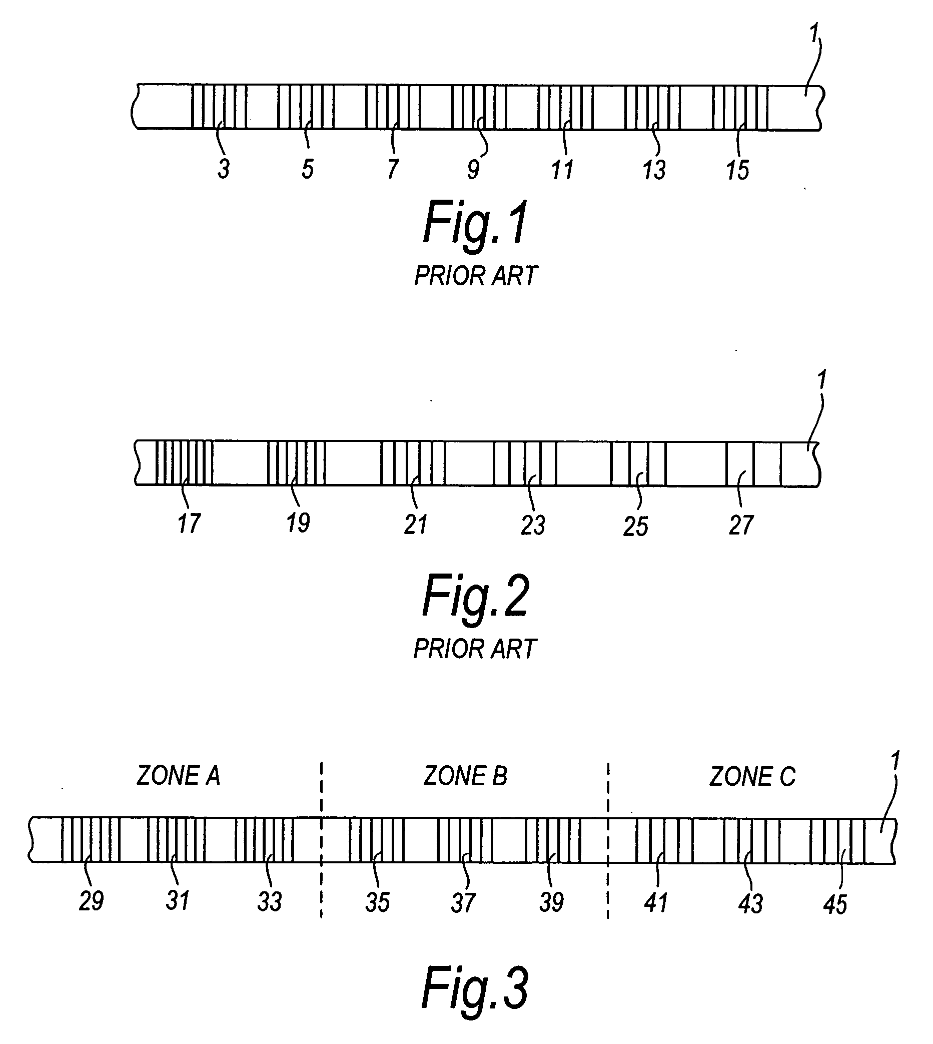
[0024]FIG. 1 shows a prior art arrangement of a fibre optic cable 1 with a plurality of substantially identical fibre Bragg gratings 3 to 15 formed thereon, each fibre Bragg grating possessing the same grating pitch / period. A fibre Bragg grating sensor could be created utilising such a fibre optic cable 1. In such a sensor, the Bragg wavelength of the reflected light from each fibre Bragg grating 3 to 15 would be the same due to the identical grating period of each fibre Bragg grating. If a spatial and / or temperature variation was to occur in the vicinity of, for example, fibre Bragg grating 11, the Bragg wavelength of the reflected light from fibre Bragg grating 11 would be shifted because the distance between adjacent elements of the grating 11 is altered. This wavelength shift could be detected, and so the spatial and / or temperature variation can be sensed. The problem with this prior art arrangement is that the Bragg wavelength of the reflected light from each fibre Bragg gratin...


PUM


Abstract

A method and device for sensing spatial variations and/or temperature variations in the locality of a fibre optic cable 1 is disclosed, wherein a broadband light source 47 is used to shine incident light onto a series of fibre Bragg gratings contained within zones A, B and C. Each zone contains a plurality of fibre Bragg gratings, the plurality of fibre Bragg gratings in any one zone having a substantially identical grating period, and the fibre Bragg gratings in the respective zones having different grating periods. The reflected light from each fibre Bragg grating is returned back down the fibre optic cable 1 and redirected via a 2×1 coupler 51 to a wavelength detection system 53 and a personal computer 63. The combination of wavelength detection system 53 and personal computer 63 allow analysis of the reflected light patterns, as well as providing a user interface which enables detection of the occurrence of a spatial and/or a temperature variation. The location of the said variation along the fibre optic cable 1 is advantageously detectable in terms of the particular zone A, B or C in which the said variation has been sensed.

Description

BACKGROUND OF THE INVENTION [0001] This invention relates to a fibre optic cable, to a method of sensing spatial variations and / or temperature variations in a structure using a fibre optic cable, and to a device for sensing spatial variations and / or temperature variations in a structure, comprising a fibre optic cable. [0002] The use of fibre Bragg gratings in sensors is well known. U.S. Pat. No. 4,761,073 (incorporated herein by reference) describes a spatially resolving fibre optic cable strain gauge which utilises fibre Bragg gratings, and it is also known to use similar fibre Bragg grating sensors to monitor variations in temperature. Variations are able to be sensed as the period and the effective refractive index of a fibre Bragg grating are altered as a result of a change in strain or a change in the ambient temperature in the locality of the fibre Bragg grating. However, fibre Bragg grating sensors forming the prior art suffer from a lack of spatial accuracy, and as a result...

Claims


Application Information

Patent Timeline
IPC IPC(8): G01K11/32G01L1/24
CPCG01L1/242G01K11/3206G01B11/165G01L1/246
Inventor GRATTAN, KENNETH THOMAS VICTORSUN, TONGZHAO, WEIZHONG
Owner KIDDE IP HLDG
Why Eureka
Try Eureka