Spilway with improved dissipation efficiency

a technology of dissipation efficiency and pipeline, applied in the field of civil engineering, can solve the problems of large increase of flow discharge, loss of excess kinetic energy, and significant increase of non-dissipated kinetic energy

Inactive Publication Date: 2005-05-26
CIUHA DUSAN
View PDF6 Cites 11 Cited by
  • Summary
  • Abstract
  • Description
  • Claims
  • Application Information

AI Technical Summary

Benefits of technology

[0024] Accordingly, the present invention relates to a spillway of a hydro power plant weir or similar hydraulic structure, consisting the consolidated stilling basin, which is located—when observed in the flow-direction—directly behind the spillway chute and when desired also concluded with the end sill and on the sides constrained with at least essentially vertical or inclined side walls. When desired, in the area of such spillway, a suitable gate or similar closing structure is proposed. The above mentioned stilling basin with the spillway chute and if / when required with the end sill together with the mentioned side walls represents the uniform, compact structure for the control of the hydraulic forces and other phenomena, between the reservoir area of each river channel, that takes place above / before the mentioned spillway and the downstream river channel with the corresponding banks behind / below the dissipation area.

Problems solved by technology

For this reason at the hydraulic structures, there always is a need for the loss of the excess kinetic energy, therefore must be dissipated, because the excess energy would cause extensive erosion effects of the downstream river channel bottom and banks, not only to / for immediately behind from the stilling basin, but also on a considerable downstream distance, as well.
The problems arise at an enormous increases of flow discharge, as at so changed conditions (at increased of flow discharge and at increased approach energy head, as well) the portion of the non-dissipated kinetic energy significantly increases and threatens the tailwater river channel behind the hydraulic structure.
The water flow over such structures, with which in general may be arrange even at already existing hydraulic structures and that are being up to the certain arrangement supplement in this way, may actually cause certain dissipation, but only in the case of the adequately discharge at the adequately head, what means at large enough Froude numbers.
The theoretical calculations as well as the results acquired through practice are showing, that at the small heads or under the lower limit value of the Froude number such solutions have no effect and therefore they are meaningless.
Modification of the existing structures using this approach, requires breaking of the huge quantities of concrete in the stilling basin area, lowering the bottom and repeated concreting, which is not economically feasible and is therefore irrational.
It should be mentioned, that even the designing of the new structure with the adequately lowered stilling basin bottom tremendous increases the investment costs of the structure.
However, an important disadvantage of the described construction has to be taken into account.
The transversal beams unavoidable reduce the effective water cross profile and in fact more-less reduce discharge outflow capacity from the inclined rectangular channel.
This is especially problematic, when appreciable amount of debris, trash, bushes, part of trees or tumbleweeds is accompanid to the flow, since these parts may become lodged between the beams and in inclined section under the beams, which leads to essential restricting the flow.
In addition, removal of this material is sometimes very difficult.

Method used


Image

  • Spilway with improved dissipation efficiency
  • Spilway with improved dissipation efficiency
  • Spilway with improved dissipation efficiency

Examples


Embodiment Construction

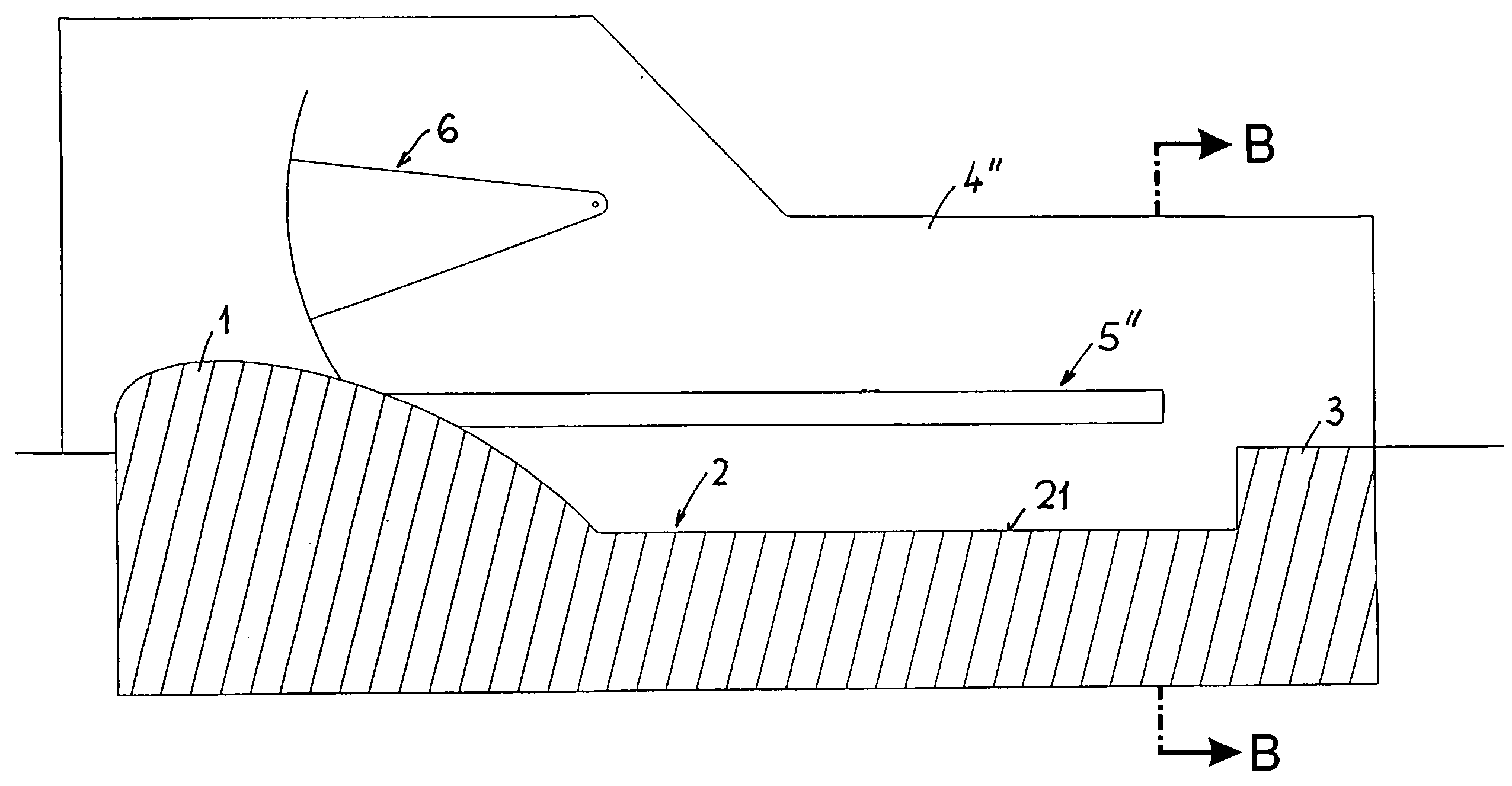
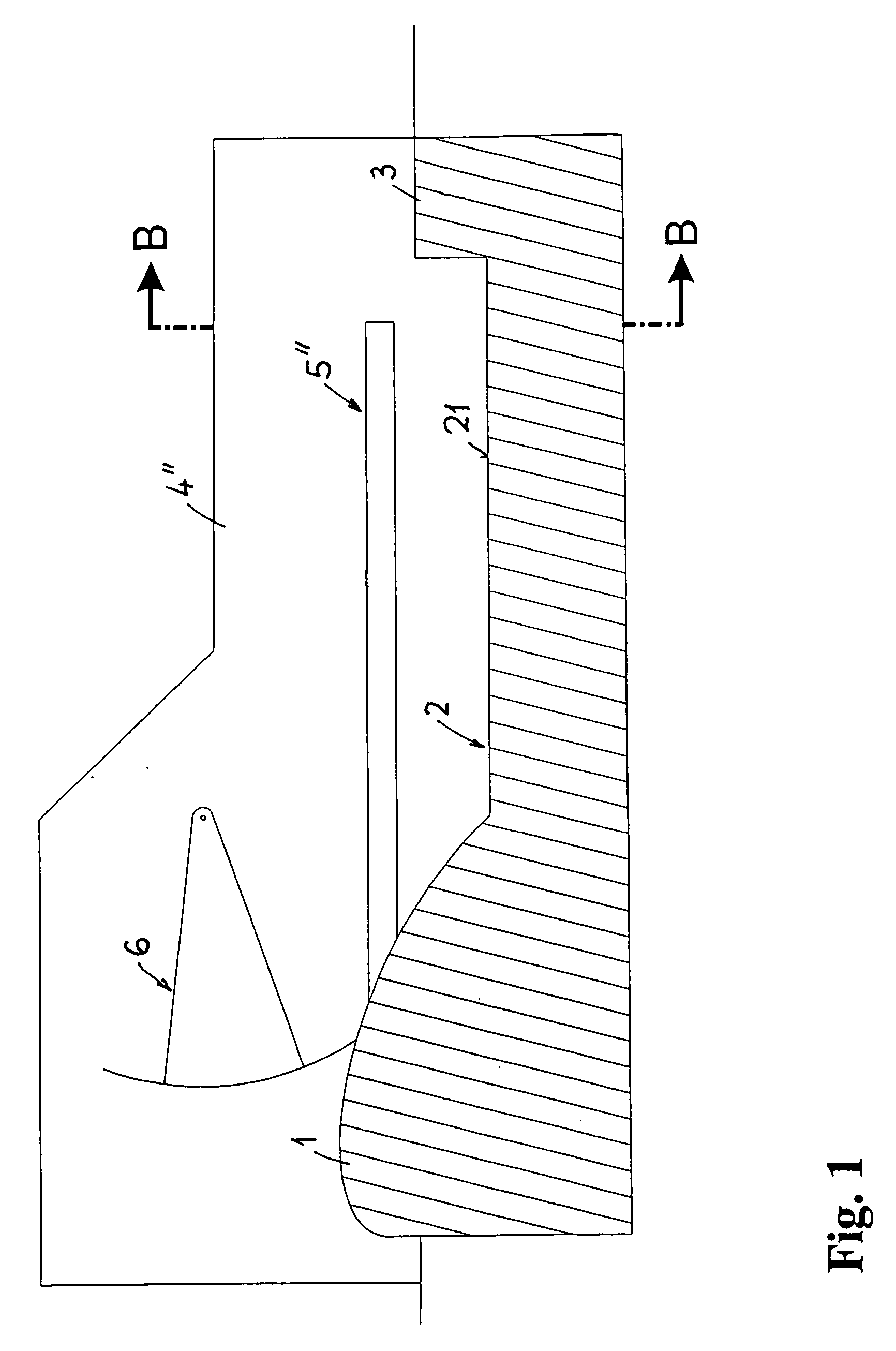
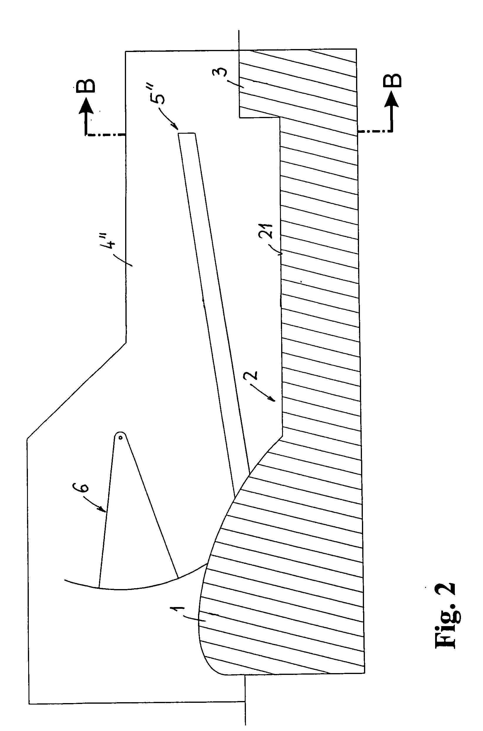
[0086] The spillway, e.g. of a hydro power plant weir or similar hydrauic structure with the improved dissipation efficiency according to the invention is presented on the FIG. 1 in the longitudinal cross-section along the plane A-A according to FIGS. 11 and / or 12, and on FIG. 11 and 12 in the transversal section in the section B-B according to FIG. 1 or rest FIGS. 2 to 10. The spillway—when observed in the flow direction—in principle consists of overflow spillway 1, stilling basin 2 with the end sill 3 or without it, and is on sides constrained with the side walls 4′, 4″, that are running in the flow direction.

[0087] If needed or depending on the purpose of the spillway, the gate 6 or similar closing device may be positioned in the field of spillway area, that are quite schematically presented in FIGS. 1 to 10, but in a quite understandable manner for those skilled in the art. At the construction of the spillway, presented on FIG. 12, the sidewalls 4′, 4″ are flat and vertical, wh...


PUM


Abstract

The purpose of the present invention is to obtain efficiency of dissipation or loss of the excess kinetic energy, at each required spillway of the even at relatively low approach of energy heads and relatively high discharges, which means at very low Froude numbers and by negligible decrease of the interior transversal cross-section of each required spillway by the designing of new hydraulic structures or even only on the basis of economically acceptable reparation each required of the already existing structures, the effective dissipation and/or loss of excess kinetic energy and thus prevent the bottom and banks of each required river channel downstream from the spillway against extensive erosion. The spillway consists of the consolidated stilling basin (2) positioned directly below/behind the spillway (1) and if/when required it is concluded with the end sill (3) and at the sides constrained with vertical or inclined side walls (4′, 4″). If required, in the area of such spillway there is an appropriate gate (6) or end sill (3) together with the side walls (4′, 4″), which represents a uniform, compact structure available to withdraw the hydraulic loadings and other phenomena, which occur between the impounding reservoir area of each stream flow arranged upstream/before the spillway and the tailwater river channel with the river banks below/behind the spillway area. According to the invention there, in the area at least one of the side walls (4′, 4″) of the spillway, at least one dissipation beam (5′, 5″) is foreseen, which extends at least essentially in the flow direction and protrudes from the side into the interior of the spillway.

Description

FIELD OF THE INVENTION [0001] The invention generally belongs to the domain of civil engineering, namely the field of river regulations, or even more to the devices for the dissipation and / or loss of excess kinetic energy. BACKGROUND OF THE INVENTION [0002] The present invention is based on the problem, how to achieve, at each required spillway of the hydro power plant weir or similar hydraulic structure, even at relatively small approach energy heads and relatively high discharges, i.e. at very low Froude numbers, and by negligible decrease of interior transversal cross-section of the spillway by the construction of new hydraulic structures or even only on the basis of an economically acceptable modification of an existing structure, the effective dissipation and / or loss of excess kinetic energy and thus prevent the bottom and banks of each required river channel downstream from the spillway against extensive erosion. [0003] Hydraulic structures as hydro power plant weirs and simil...

Claims


Application Information

Patent Timeline
Patent Type & Authority Applications(United States)
IPC IPC(8): E02B8/06
CPCE02B8/06
Inventor CIUHA, DUSAN
Owner CIUHA DUSAN
Why Eureka
Try Eureka