Construction of static structures for gas turbine engines

a gas turbine engine and static structure technology, applied in the direction of machines/engines, mechanical equipment, coatings, etc., can solve the problems of engine subjected to extreme temperatures and high stress levels, structural damage such as cracking of components, and engine subjected to foreign matter

Inactive Publication Date: 2005-05-26
FLORIDA TURBINE TECH
View PDF3 Cites 36 Cited by
  • Summary
  • Abstract
  • Description
  • Claims
  • Application Information

AI Technical Summary

Benefits of technology

[0008] An object of this invention is to fabricate static power plant components from a foam metal, coat the same with a thermal barrier or ceramic coating and include air inlet or exit openings to cool

Problems solved by technology

As is well known in the power plant technology, one of the more insidious problems associated with gas turbine engines and particularly those powering aircraft is the structural damage such as cracking of the components that operate in these hostile environments.
Hence, not only is the engine subjected to extreme temperatures and high stress levels, it is also subjected to foreign matter that is ingested in the inlet of the engine.
In heretofore known materials being utilized in current day engines, a crack or crevice developed in a component tends to propagate and if not attended to within a given time period, this part can lead to a failure of the part and ultimately to an engine failure.
A

Method used


Image

  • Construction of static structures for gas turbine engines
  • Construction of static structures for gas turbine engines
  • Construction of static structures for gas turbine engines

Examples


Embodiment Construction

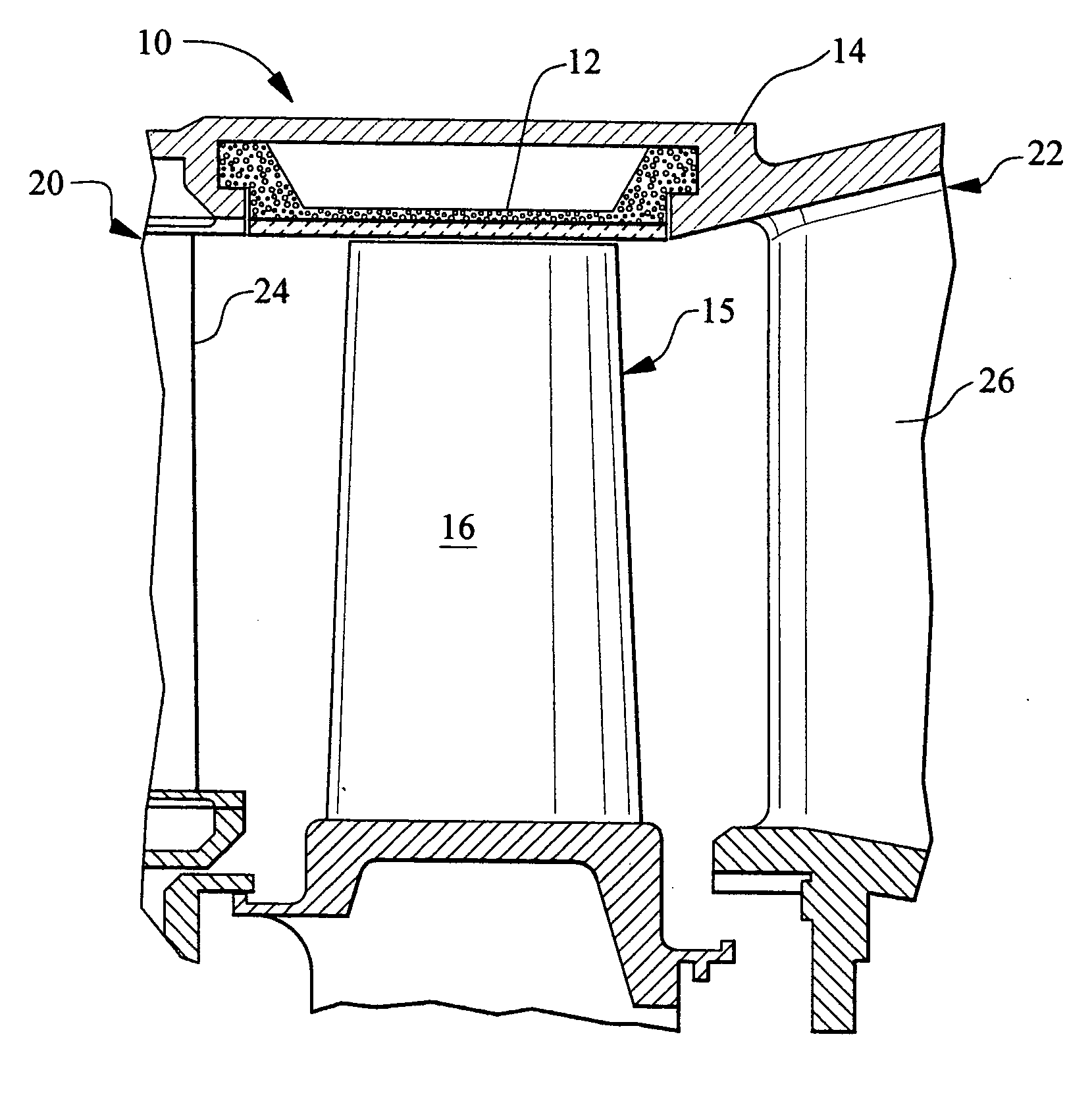
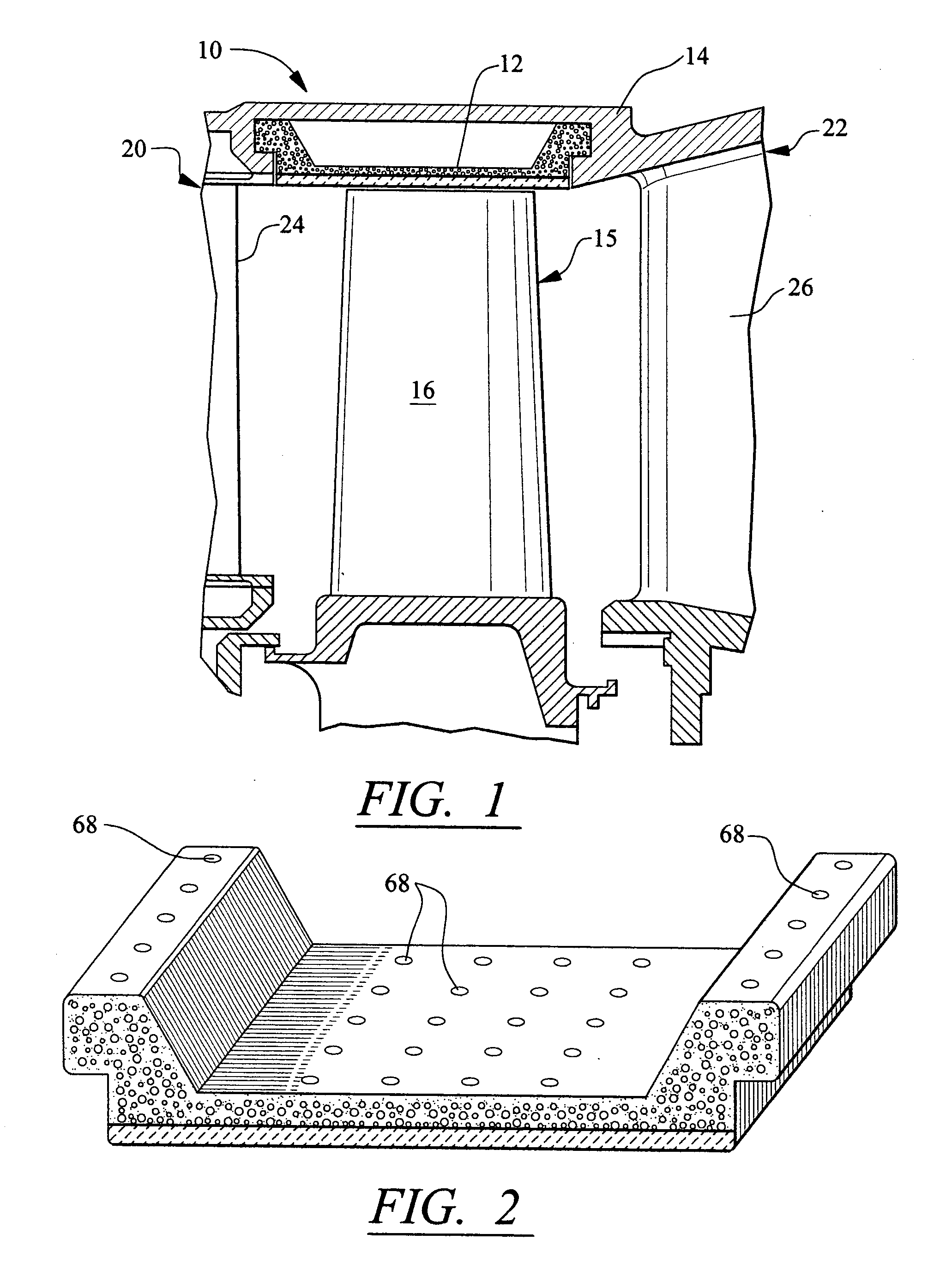
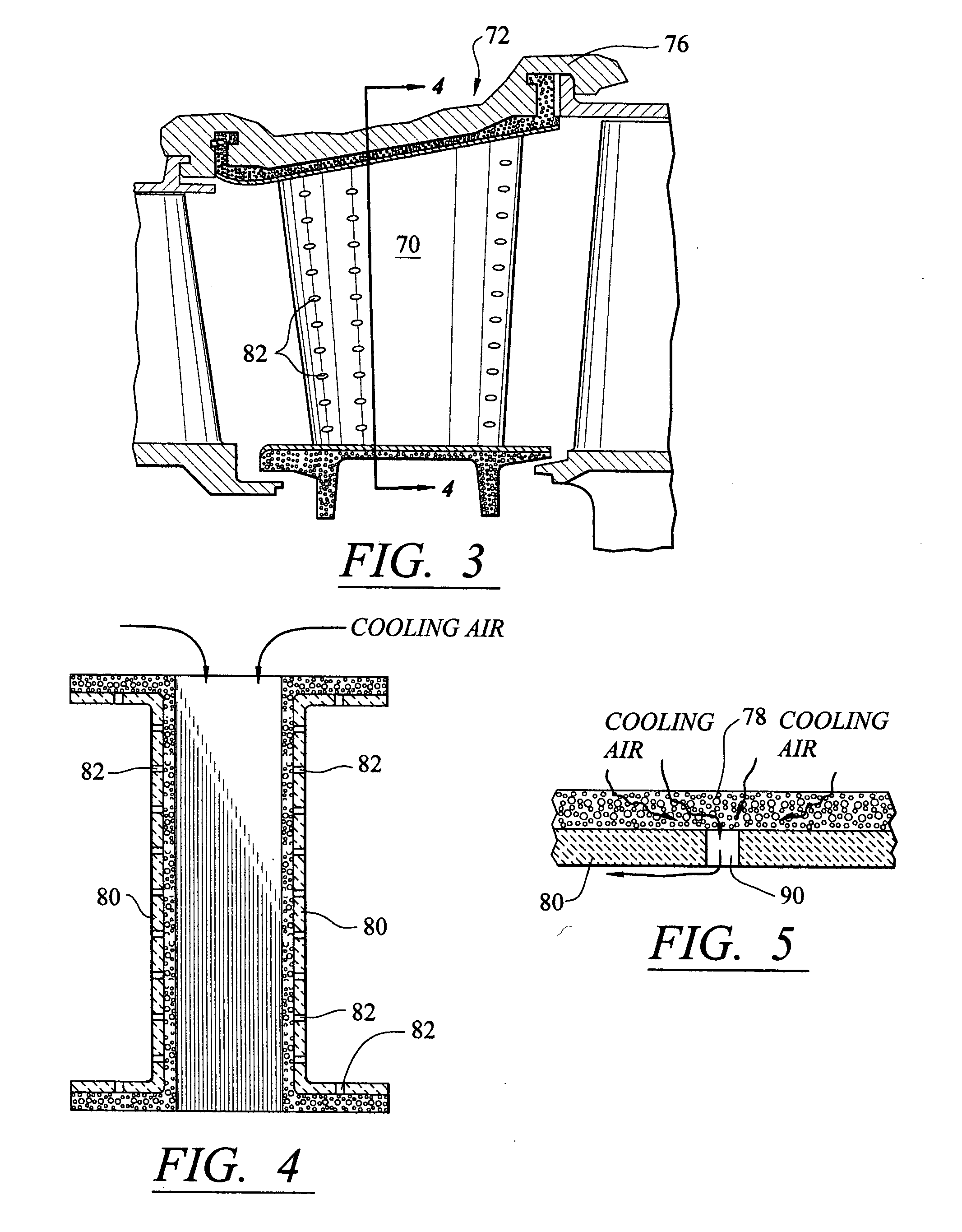
[0018] While the preferred embodiment of this invention is directed to bladed outer air seals, sometimes referred to as BOAS, and vanes of a stator vane assembly for gas turbine engines, as one skilled in this art will realize, other components of the gas turbine engine may lend themselves to utilize the invention. What is deemed important in this invention is that the substrate has minute holes that serve as a bond or integral bond of the coating so that the coating does not have a tendency to peel and hence, the crack or blemish stays localized to enhance the repair of the part. Additionally, the particular coating material and the method of application that is utilized may vary from component to component and for various engine applications. The coatings referred to in this patent application are well known coatings utilized in turbine power plant technology and any appropriate state-of-the art coatings utilized with this invention are deemed to be within the scope of this invent...


PUM

PropertyMeasurementUnit
Porosityaaaaaaaaaa

Abstract

Porous or foam metal is utilized in certain static gas turbine engine components that includes the main body of the metal and a coating such as TBC or ceramics. Because of the porosity of the metal the coating bonds to the interstices and hence, eliminates peeling. The outer air seal for the turbine and the vanes of the stator vane assembly are examples of components constructed in accordance with this invention. Cooling is obtained by providing inlet cooling holes into the porous material and exit cooling holes in the coating so as to cool the component and apply a surface of cooling air adjacent to the exterior surface of the coating.

Description

FEDERALLY SPONSORED RESEARCH [0001] None TECHNICAL FIELD [0002] This invention relates to static structures in gas turbine engines and more particularly to these structure that are fabricated from foam metal material and judiciously coated. BACKGROUND OF THE INVENTION [0003] As is well known in the power plant technology, one of the more insidious problems associated with gas turbine engines and particularly those powering aircraft is the structural damage such as cracking of the components that operate in these hostile environments. Needless to say, because of the enormous costs in original and replacement components like vanes and seals, there is a tremendous need in the industry to provide a suitable material that minimizes the repair technique that will not only serve to repair the damaged component, but also to add life to these components and improve performance. [0004] The turbine power plant typically consists of an air inlet, a fan / compressor section, a diffuser, a combusto...

Claims


Application Information

Patent Timeline
IPC IPC(8): F01D5/18F01D5/28F01D25/12
CPCF01D5/183F05D2300/612F01D5/284F01D5/288F01D25/12Y02T50/67Y02T50/676F05D2260/202F05D2230/312F05D2230/313F05D2230/314F05D2260/203F05D2230/90F05D2300/611F01D5/186Y02T50/60
Inventor METHENY, ALFRED PAUL
Owner FLORIDA TURBINE TECH
Why Eureka
Try Eureka