Micro flow passage device, connection device, and method of using the devices

Inactive Publication Date: 2005-05-26
OLYMPUS CORP
View PDF4 Cites 22 Cited by
  • Summary
  • Abstract
  • Description
  • Claims
  • Application Information

AI Technical Summary

Benefits of technology

[0008] It is an object of the present invention, in view of the conventional problems, to provide a minute flow channel device and a joining device for the minute flow channel device, whereby the joining for injecting and discharging a substance such as fluid or gas can be automatized and perform

Problems solved by technology

In the first conventional example, however, since the pipe pressing and the precise pipe adhesion are required, the reliability of sealing the joint between the pipes and the openings of the minute flow channel device are degraded and the productivity of minute flow channel device is also degraded so that the production cost of minute flow channel device is increased.
Moreover, it is difficult to automatize the tube pressing against the pipes.
In the second and the third conventional exa

Method used


Image

  • Micro flow passage device, connection device, and method of using the devices
  • Micro flow passage device, connection device, and method of using the devices
  • Micro flow passage device, connection device, and method of using the devices

Examples


first embodiment

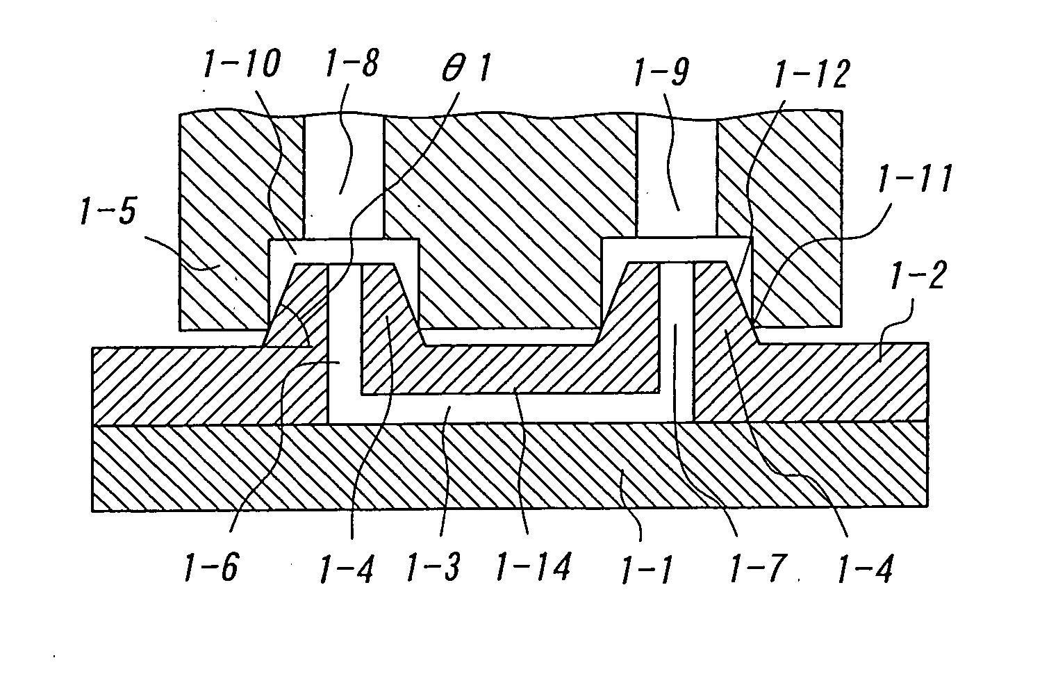
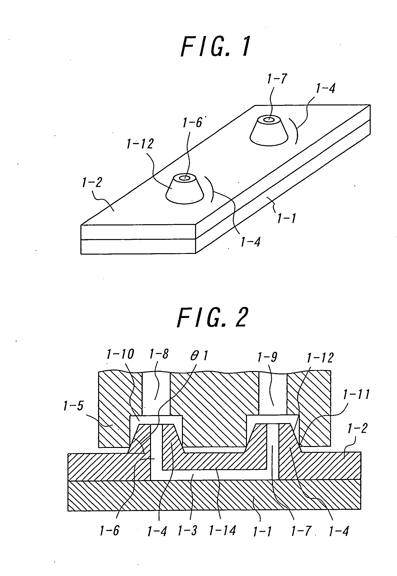
[0052]FIGS. 1 and 2 relate to a first embodiment according to the present invention. FIG. 1 is a perspective view illustrating a minute flow channel device relating to the first embodiment, and FIG. 2 is a cross sectional view illustrating the combination of the minute flow channel device illustrated in FIG. 1 and a joining device which is joined with the minute flow channel device.

[0053] The illustrated minute flow channel device includes a substrate 1-1 and an elastomer 1-2 which are bonded each other. A ditch to constitute a flow channel are formed at either or both of the bonded surfaces of the substrate 1-1 and the elastomer 1-2. In this embodiment, as illustrated in FIG. 2, a ditch 1-14 is formed at the bonded surface of the elastomer 1-2 to constitute a flow channel 1-3, and through-holes are formed so as to be communicated with the flow channel 1-3 to constitute inlet 1-6 and outlet 1-7 for a substance such as fluid or gas.

[0054] Moreover, convex joints 1-4 are formed arou...

second embodiment

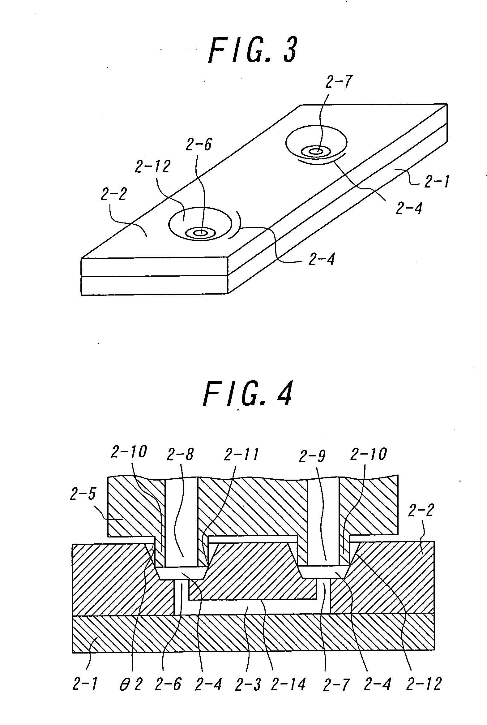
[0065]FIGS. 3 and 4 relate to a second embodiment according to the present invention. FIG. 3 is a perspective view illustrating a minute flow channel device relating to the second embodiment, and FIG. 4 is a cross sectional view illustrating the combination of the minute flow channel device illustrated in FIG. 3 and a joining device which is joined with the minute flow channel device.

[0066] In this embodiment, the illustrated minute flow channel device includes a substrate 2-1 and an elastomer 2-2 which are bonded each other, as the first embodiment. A ditch 2-14 is formed at the bonded surface of the elastomer 2-2 to constitute a flow channel 2-3, and through-holes are formed so as to be communicated with the flow channel 2-3 to constitute inlet 2-6 and outlet 2-7 for a substance such as fluid or gas. Also, in this embodiment, concave joints 2-4 are formed around the inlet 2-6 and the outlet 2-7 with the integration with the elastomer 2-2, different from the first embodiment. In t...

third embodiment

[0070]FIGS. 5 through 7 relate to a third embodiment according to the present invention. FIG. 5 is a perspective view illustrating a minute flow channel device relating to the third embodiment, and FIG. 6 is a cross sectional view illustrating the combination of the minute flow channel device illustrated in FIG. 5 and a joining device which is joined with the minute flow channel device. FIG. 7 is a perspective view illustrating components of the combination illustrated in FIG. 5. FIGS. 7(a) and (b) are perspective views illustrating the joining device and the minute flow channel device, respectively, and FIGS. 7(c) and (d) are perspective views illustrating the elastomer and the substrate of the minute flow channel device, respectively. The minute flow channel device illustrated in FIG. 7(b) is constructed of the substrate 3-1 illustrated in FIG. 7(d) and the elastomer 3-2 illustrated in FIG. 7(c) which are bonded each other. The combination illustrated in FIGS. 5 and 6 is construct...


PUM

PropertyMeasurementUnit
Angleaaaaaaaaaa
Angleaaaaaaaaaa
Adhesivityaaaaaaaaaa

Abstract

A substrate and an elastomer are bonded each other, and then, a ditch is formed at the bonded surface of the substrate or the elastomer to constitute a flow channel and thus, to constitute a minute flow channel device with the flow channel. Then, a through-hole functioning an inlet and/or outlet is formed at the elastomer so as to be communicated with the flow channel. Then, a convex or concave joint is formed at the elastomer with integration so as to be opened outward from the through-hole so that the inclination angle of said joint is set to not less than 45 degrees and less than 90 degrees. Then, a joining device is pressed and joined with the minute flow channel device via the joint. Therefore, the connection for injecting and discharging a substance such as fluid or gas can be easily realized and automatized, and the device exchange can be performed easily.

Description

FIELD OF THE INVENTION [0001] This invention relates to a minute flow channel device with a minute flow channel, a joining device which is joined with the minute flow channel device for injecting and discharging a substance such as fluid or gas in and out of the minute flow channel of the minute flow channel device, and a method for using the minute flow channel device. DESCRIPTION OF THE PRIOR ART [0002] For injecting and discharging a substance such as fluid or gas in and out of a minute flow channel of a minute flow channel device, it is required to join a joining device exclusively for injecting and discharging with the minute flow channel device. [0003] Such a minute flow channel device and such a joining device as mentioned above are exemplified in “NOVEL INTERCONNECTION AND CHANNEL TECHNOLOGYIES FOR MICROFLUIDICS”, N. J. Mourlas et al., Proceedings of the μTAS'98 Workshop (Document 1), where a plurality of openings are formed at a minute flow channel device to be functioned a...

Claims


Application Information

Patent Timeline
IPC IPC(8): B01J19/00B01L3/00G01N1/00C12M1/00C12N15/09G01N37/00
CPCB01J19/0093B01J2219/00783B01J2219/00813B01J2219/00828B01J2219/00831B01J2219/00833B01L2300/123B01L3/502707B01L3/502715B01L2200/026B01L2200/027B01L2200/0689B01L2200/12B01J2219/00891
Inventor FUNAZAKI, JUNSHINOHARA, ETSUO
Owner OLYMPUS CORP
Why Eureka
Try Eureka