Power transmission mechanism
a transmission mechanism and power technology, applied in mechanical equipment, transportation and packaging, gears, etc., can solve the problems of increasing manufacturing costs, affecting increasing manufacturing costs, so as to reduce the positioning accuracy of constituent gears, increase manufacturing costs, and facilitate machine operation
- Summary
- Abstract
- Description
- Claims
- Application Information
AI Technical Summary
Benefits of technology
Problems solved by technology
Method used
Image
Examples
first embodiment
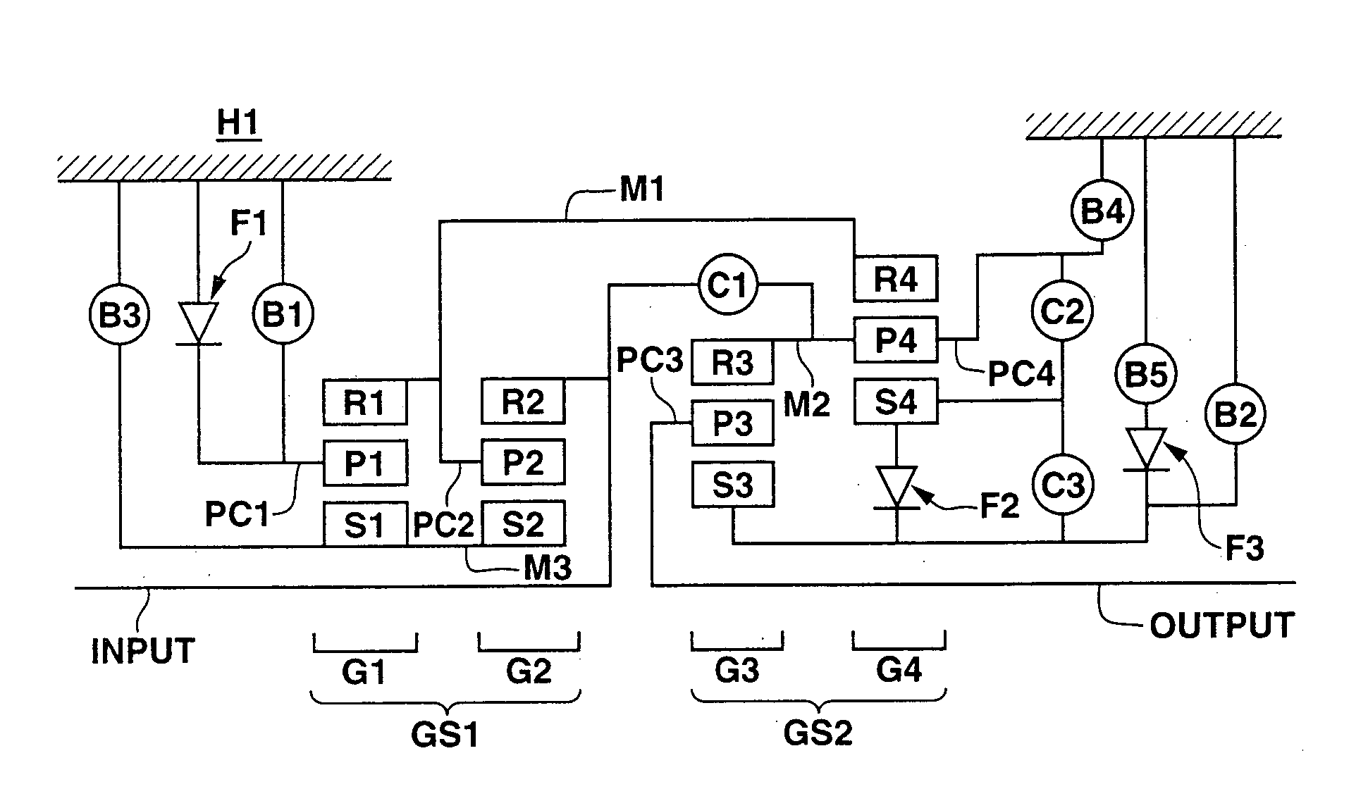
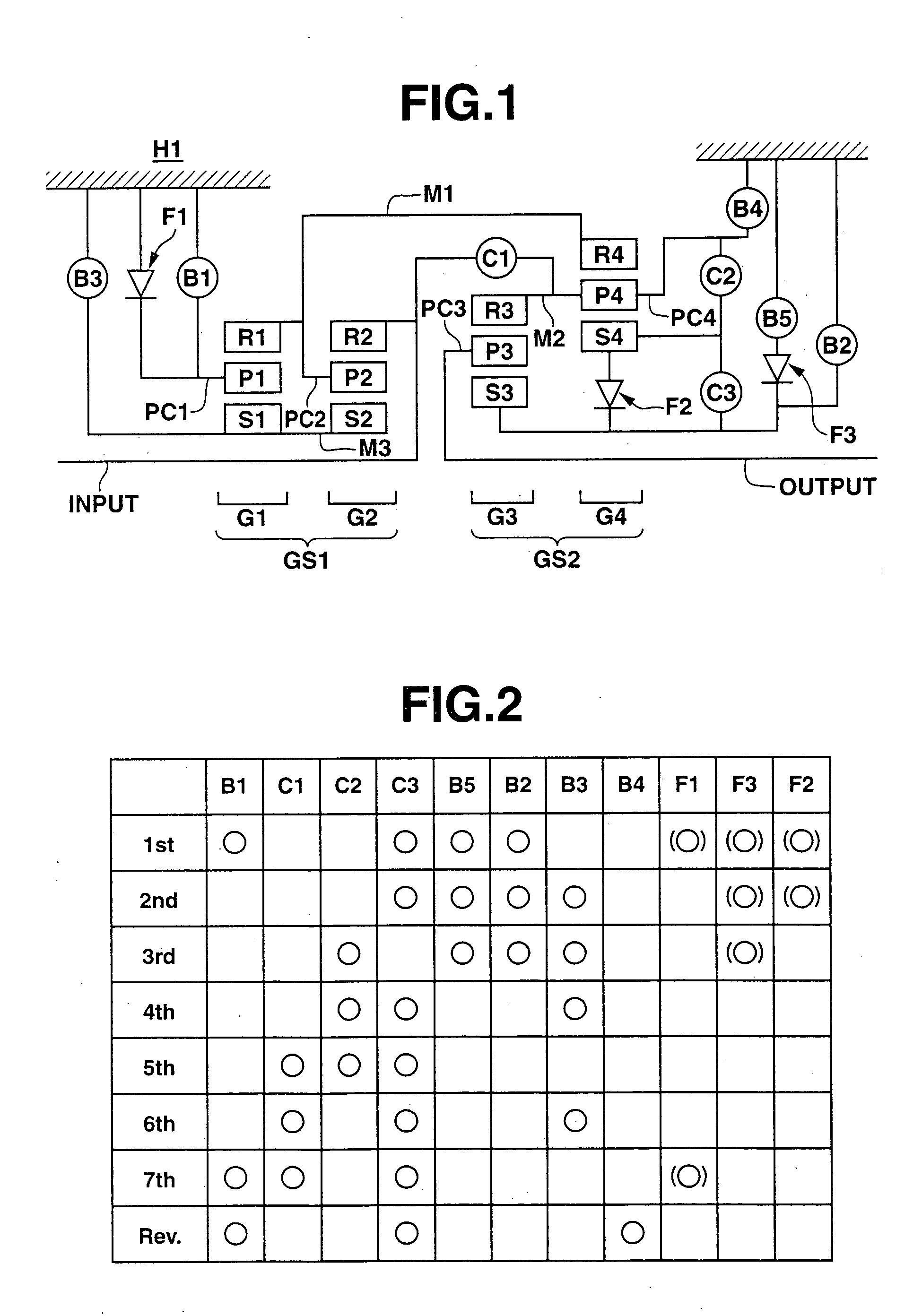
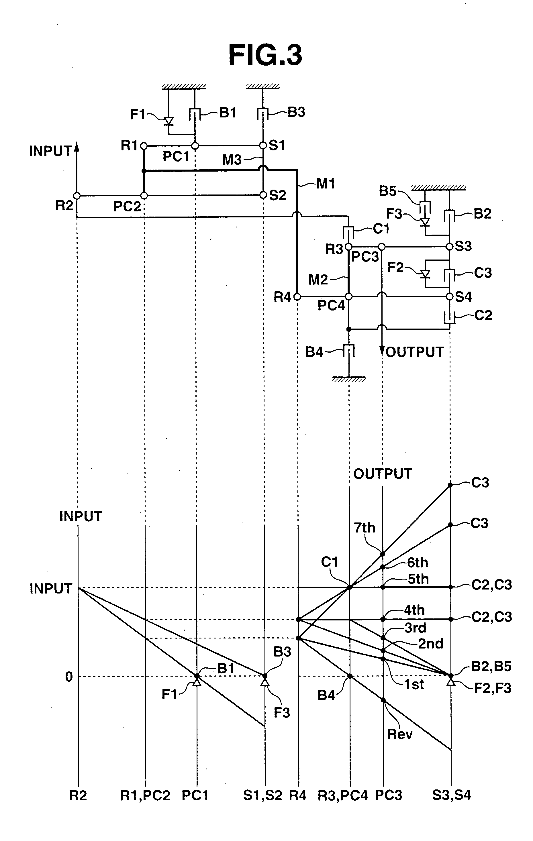
[0032]FIG. 1 is a schematic diagram depicting a power transmission mechanism of an automatic transmission for a front-engine, rear-drive vehicle, configured to establish seven forward speeds and one reverse speed, in accordance with the present invention. There are arranged a first planetary gearset GS1 including a first planetary gear G1 and a second planetary gear G2, nearer to an input shaft INPUT (on the left side of FIG. 1), and a second planetary gearset GS2 including a third planetary gear G3 and a fourth planetary gear G4, nearer to an output shaft OUTPUT (on the right side of FIG. 1). In a transmission housing H1 are mounted a plurality of torque transmitting devices. More specifically, a first clutch C1, a second clutch C2, a third clutch C3, a first brake B1, a second brake B2, a third brake B3, a fourth brake B4, and a fifth brake B5 are disposed in transmission housing H1. In addition, a plurality of one-way clutches including a first one-way clutch F1, a second one-way...
third embodiment
[0091]FIG. 19 is a schematic diagram depicting a power transmission mechanism of an automatic transmission for a front-engine, rear-drive vehicle, configured to establish seven forward speeds and one reverse speed, in accordance with the present invention. FIG. 20 is shows in tabular form clutch and brake engagements required to establish the seven forward speeds and the reverse speed in the power transmission mechanism of FIG. 19.
[0092] In addition to the constituent elements as employed in the first embodiment, this power transmission mechanism includes an eighth brake B8 and a fourth one-way clutch F4 in parallel to third brake B3. In this embodiment, eighth brake B8 is engaged while third brake B3 is engaged. However, it is not essential to engage both of the brakes. Only eighth brake B8 may be engaged in accordance with a desired capacity of torque transmission.
[0093] In the gear shift from the fourth speed to the fifth speed, the transmission controller disengages third brake...
fourth embodiment
[0094]FIG. 21 is a schematic diagram depicting a power transmission mechanism of an automatic transmission for a front-engine, rear-drive vehicle, configured to establish eight forward speeds and one reverse speed, in accordance with the present invention. FIG. 22 shows in tabular form clutch and brake engagements required to establish the eight forward speeds and the reverse speed in the power transmission mechanism of FIG. 21.
[0095] In addition to the constituent elements as employed in the second embodiment, this power transmission mechanism includes an eighth brake B8 and a fourth one-way clutch F4 in parallel to third brake B3. This transmission produces same effects as in the third embodiment.
PUM
 Abstract
Description
Claims
Application Information
 - R&D
- Intellectual Property
- Life Sciences
- Materials
- Tech Scout
- Unparalleled Data Quality
- Higher Quality Content
- 60% Fewer Hallucinations
Browse by: Latest US Patents, China's latest patents, Technical Efficacy Thesaurus, Application Domain, Technology Topic, Popular Technical Reports.
© 2025 PatSnap. All rights reserved.Legal|Privacy policy|Modern Slavery Act Transparency Statement|Sitemap|About US| Contact US: help@patsnap.com


