Method for power quality summary and trending

Active Publication Date: 2005-05-26
SQUARE D CO
View PDF7 Cites 17 Cited by
  • Summary
  • Abstract
  • Description
  • Claims
  • Application Information

AI Technical Summary

Benefits of technology

[0004] Since the analysis of accumulated electrical data is a complex process, it is desirable to be able to present an analysis in an accessible and easy to use manner while preserving the mass of collected data for other complex pro

Problems solved by technology

The evaluation of power quality within an industrial, commercial or institutional fa

Method used


Image

  • Method for power quality summary and trending
  • Method for power quality summary and trending
  • Method for power quality summary and trending

Examples


Embodiment Construction

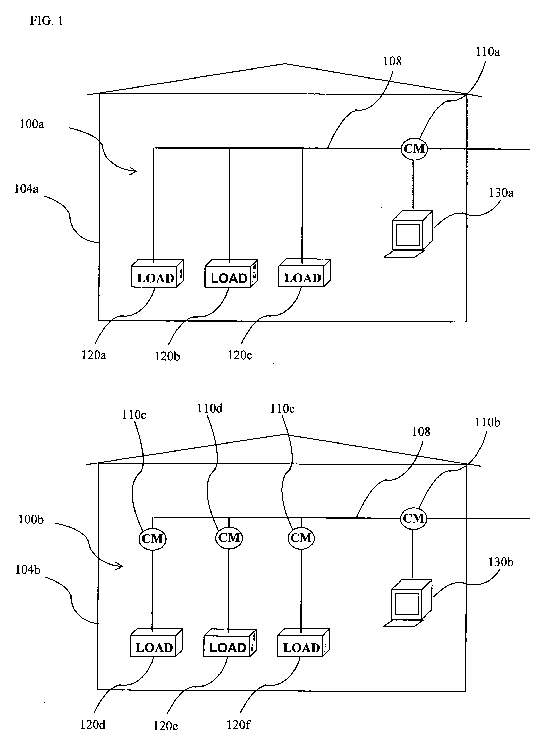
[0037] Referring now to the drawings, and initially to FIG. 1, a block diagram of a power distribution system 100a, according to one embodiment of the present invention is shown. The power distribution system 100a provides power to a facility 104a. Within the facility 104a the power is monitored by a circuit monitor 110a which is optionally networked to a computer system 130a. The electrical power is distributed with the plant 104a to a series of loads 120a-c. The power distribution system 100a thus represents a system with a single central power monitoring device 110a.

[0038] Another power distribution system 100b is shown distributing power within a facility 104b, according to another embodiment of the present invention. In this scenario there is a central circuit monitor 110b and branch circuit monitors 120d-e supplying electrical power to loads 120d-f respectively. The circuit monitors are optionally networked together and with a central computer system 130b.

[0039] In yet anoth...


PUM


Abstract

A system for accumulating and evaluating electromagnetic phenomena of at least one power quality category of a power distribution system, using a circuit monitor or processing system that summarizes and trends electromagnetic phenomena. The system provides for expressing the power quality index as a single number for each power quality category present and for combining multiple power quality indices into a single overall power quality index.

Description

FIELD OF THE INVENTION [0001] This invention is directed generally to the evaluation of power quality within an industrial, commercial or institutional facility. The invention provides a method for accumulating, summarizing, and trending data pertinent to the evaluation of power quality and involves the monitoring and evaluation of several electromagnetic phenomena. SUMMARY OF THE INVENTION [0002] The evaluation of power quality within an industrial, commercial or institutional facility is a complicated job requiring specialized equipment, training and experience. Therefore, a method is required for accumulating, summarizing and trending data pertinent to the evaluation of power quality, which can be incorporated in a circuit monitor and / or system of circuit monitors. [0003] One of the aspects a power monitoring methodology is in the configuration of circuit monitoring equipment to collect the appropriate electrical data pertinent to the monitored facility and the load types present...

Claims


Application Information

Patent Timeline
IPC IPC(8): G01R19/25G06F19/00
CPCG01R19/2513
Inventor CURTIS, LARRY E.BICKEL, JON A.
Owner SQUARE D CO
Why Eureka
Try Eureka