
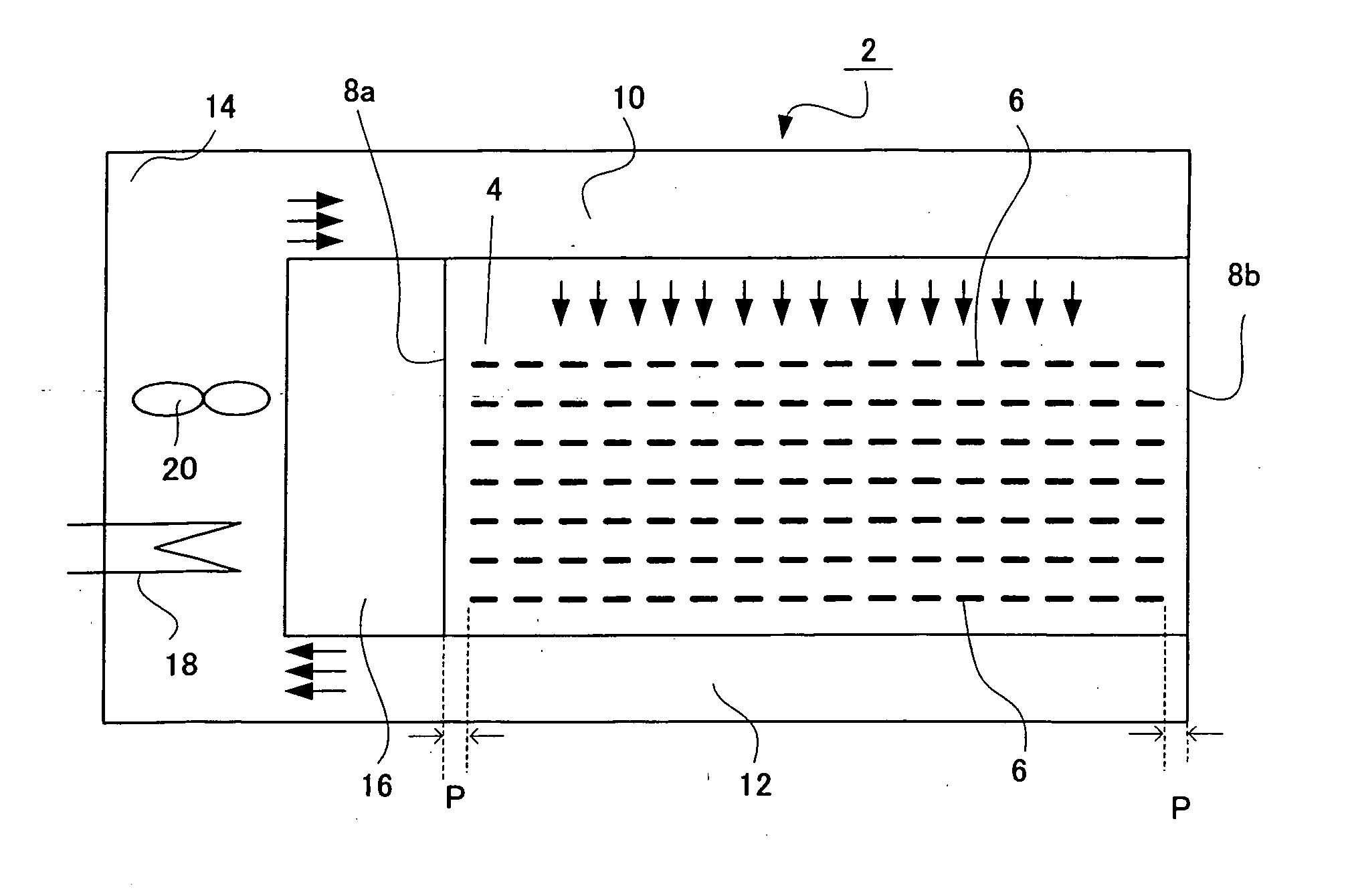
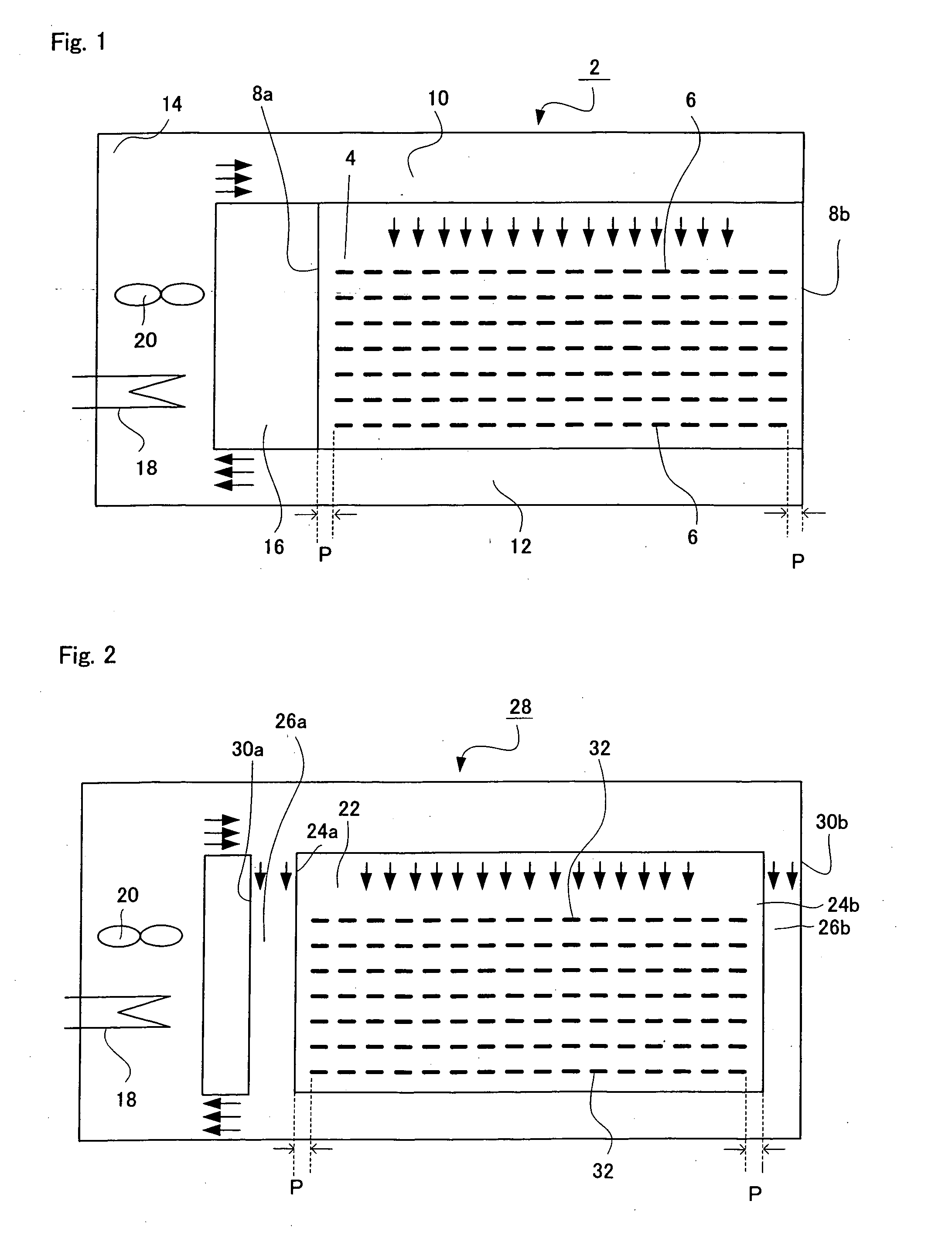
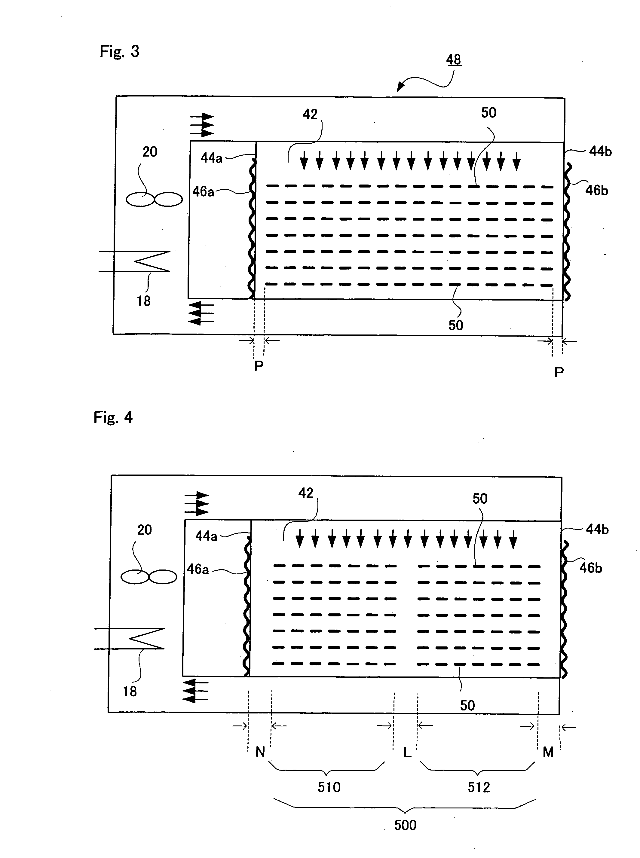
Flame resistant rendering heat treating device, and operation method for the device

a heat treatment device and flame-resistant technology, applied in the direction of dryers with progressive movements, furnaces, textiles and papermaking, etc., can solve the problems of reducing the speed of hot air passing through the path, affecting the efficiency of heat treatment, so as to achieve the effect of improving productivity without quality degradation

Active Publication Date: 2005-06-02
TOHO TAYON CO LTD
View PDF4 Cites 10 Cited by
  • Summary
  • Abstract
  • Description
  • Claims
  • Application Information

AI Technical Summary

Benefits of technology

[0022] In order to prevent this fiber breakage, a countermeasure such as lowering inside temperature or the like of heat treatment chamber is necessary. The lowering inside temperature of heat treatment chamber, however, results in lower reaction rate and consequently in lower productivity, which is contrary to intended productivity improvement.
[0027] Hence, the present invention aims at providing a heat treatment apparatus for oxidation which can uniformly conduct a heat treatment of strands for oxidation and which can give improved productivity without quality deterioration, and an operating method of the apparatus.

Problems solved by technology

The speed of hot air passing through paths tends to decrease significantly in lower paths, in particular; and breakage of fiber occurs frequently in these lower paths.
The lowering inside temperature of heat treatment chamber, however, results in lower reaction rate and consequently in lower productivity, which is contrary to intended productivity improvement.
Further, in subjecting strands to a heat treatment for oxidation using the above heat treatment apparatus for oxidation, there is a problem in that hot air leaks from the slits formed for leaving and entering of strands from and into the heat treatment chamber.

Method used


Image

  • Flame resistant rendering heat treating device, and operation method for the device
  • Flame resistant rendering heat treating device, and operation method for the device
  • Flame resistant rendering heat treating device, and operation method for the device

Examples


example 1

[0124] A heat treatment apparatus for oxidation shown in FIG. 4 was produced. The dimensions of the heat treatment chamber were length=15 m, breadth=2 m, height=1.2 m, upper duct height=0.5 m, and lower duct height=0.3 m. Two returning rollers were provided at each side of the oven for oxidation. A multi-blade fan was provided in each of the upper and lower hot air circulation ducts.

[0125] Gaps between zones and between zone and inner side wall were set at 1 cm. An electric heater was fitted to each side wall.

[0126] Into the apparatus were fed polyacrylonitrile-based fiber strands (1 dtex, 24,000 fibers / strand). The feeding speed of strands was 300 m / hr and a hot air of 1.1 m / sec and 260° C. was fed to the uppermost path.

[0127] The electricity applied to the side wall heaters was controlled to keep the temperature difference between side wall temperature and heat treatment chamber inside average temperature within 5° C. Thereby, the speed of the hot air passing through intermedia...

example 2

[0128] A heat treatment apparatus for oxidation shown in FIG. 5 was produced. The dimensions of the heat treatment chamber were length=15 m, breadth=2 m, height=1.2 m, upper duct height=0.5 m, and lower duct height=0.3 m. Two returning rollers were provided at each side of the oven for oxidation. A multi-blade fan was provided at each of the upper and lower hot air circulation ducts.

[0129] Five slits were formed in each of the front wall and the back wall. To the slits were fitted nozzles shown in FIG. 7. The injection direction of hot air was toward inside the heat treatment chamber.

[0130] Channeling-preventing plates of 15 cm in width were arranged between zones and between zone and inner side wall. Thereby, each gap was set at 1 cm.

[0131] Into the apparatus were fed polyacrylonitrile-based fiber strands (1 dtex, 24,000 fibers / strand). The feeding speed of strands was 300 m / hr and a hot air of 1.1 m / sec and 260° C. was fed to the uppermost path.

[0132] Hot air of 260° C. was fe...


PUM

PropertyMeasurementUnit
speedaaaaaaaaaa
speedaaaaaaaaaa
widthaaaaaaaaaa

Abstract

A heat treatment apparatus for oxidation having: an oven for oxidation having a heat treatment chamber having a plurality of slits through which fiber strands running horizontally leave or returned strands enter and capable of sending hot air vertically from above the fiber strands to allow the fiber strands to have oxidation, and a means for feeding hot air into the heat treatment chamber, and a plurality of returning rollers which are provided at the two outsides of the oven for oxidation and which return the fiber strands entering and leaving through said slits, into the oven for oxidation, wherein each gap formed between fiber strands and each side wall of heat treatment chamber parallel to the running direction of fiber strands running in the heat treatment chamber, or each gap formed between fiber strands and each channeling-preventing plate interposed between the side wall and the fiber strands in parallel to the running direction of fiber strands is set at 150 mm or less. The slits may be provided with a means for injecting hot air into the heat treatment chamber.

Description

TECHNICAL FIELD [0001] The present invention relates to a heat treatment apparatus for oxidation, used in production of polyacrylonitrile-based oxidation fiber (flame-resistant fiber). More particularly, the present invention relates to an apparatus used for subjecting polyacrylonitrile-based fiber strands or the like to a heat treatment for oxidation, as well as to an operating method of tile apparatus. The oxidation fiber is important as a heat-resistant fiber or as a material for production of polyacrylonitrile-based carbon fiber. BACKGROUND ART [0002] Polyacrylonitrile-based oxidation fibers have been produced by subjecting a polyacrylonitrile-based fiber to a heat treatment for oxidation in an oxidizing atmosphere of 200 to 300° C. [0003] The reaction taking place in the heat treatment of polyacrylonitrile-based fiber for oxidation is an exothermic reaction wherein oxidation and cyclization take place simultaneously. A heat treatment at a high temperature results in a high reac...

Claims


Application Information

Patent Timeline
Patent Type & Authority Applications(United States)
IPC IPC(8): D01F9/32
CPCD01F9/32
Inventor YAMAGUCHI, MASANAO
Owner TOHO TAYON CO LTD
Learn More