Portable drag compressor powered mechanical ventilator

a mechanical ventilator and compressor technology, applied in the field of medical equipment, can solve the problems of inability to deliver complex ventilation modes and or breath types, inconvenient portability, and inability to meet the needs of long-term ventilation or long-term ventilation, and achieve the effect of minimizing fabrication inaccuracy and accurately measuring patient exhalation flow

Inactive Publication Date: 2005-06-02
BIRD PRODS
View PDF99 Cites 15 Cited by
  • Summary
  • Abstract
  • Description
  • Claims
  • Application Information

AI Technical Summary

Benefits of technology

[0067] In addition the present invention utilizes an exhalation flow transducer to accurately measure patient exhalation flow which may be utilized for determination of exhaled volume and desired triggering of inspiratory flow. In the preferred embodiment, the exhalation flow transducer is integrally formed with the exhalation valve, however, those skilled in the art will recognize that the same can be a separate component insertable into the system. To insure transducer performance accuracy, in the preferred embodiment, the particular operational characteristics of each flow transducer are stored within a memory device preferably a radio-frequency transponder mounted within the exhalation valve to transmit the specific calibration information for the exhalation flow transducer to the controller. Further, the particular construction and mounting of the flow transducer within the exhalation valve is specifically designed to minimize fabrication inaccuracies.

Problems solved by technology

A machine cycled assist breath is a breath that is triggered by the patient, but is limited and cycled by the ventilator.
While patient effort limits the flow, and hence the inspiratory volume of the breath, the ventilator may also limit the breath by providing a flow that is to low to maintain a constant pressure in the face of patient inspiratory demand.
In clinical practice, it is often times desirable to ventilate patients with oxygen FiO2 from 21% to 100%.
The prior art has included some non-complex portable ventilators which have inherent limitations as to the number and type of variables and / or parameters which may be utilized to trigger, limit and / or terminate the ventilator cycle.
Although such non-complex ventilators of the prior art are often sufficiently power efficient and small enough for portable use, their functional limitations typically render them unsuitable for long term ventilation or delivery of complex ventilation modes and or breath types.
However, these complex ventilators of the prior art have typically been too large in size, and too power inefficient, for battery-driven portable use.
Additionally, patients who require long term ventilation are not always candidates for admission to acute care hospital critical care units or may be discharged to step-down units or extended care facilities.
Many of these patients could benefit from the use of complex microprocessor controlled ventilators, but may be unable to obtain such benefit due to the non-feasibility of employing such ventilators outside of the hospital-critical care unit environment.

Method used


Image

  • Portable drag compressor powered mechanical ventilator
  • Portable drag compressor powered mechanical ventilator
  • Portable drag compressor powered mechanical ventilator

Examples


Embodiment Construction

[0085] The following detailed description and the accompanying drawings are provided for purposes of describing and illustrating a presently preferred embodiment of the invention and are not intended to describe all embodiments in which the invention may be reduced to practice. Accordingly, the following detailed description and the accompanying drawings are not to be construed as limitations on the scope of the appended claims.

A. General Description of the Preferred Ventilator System

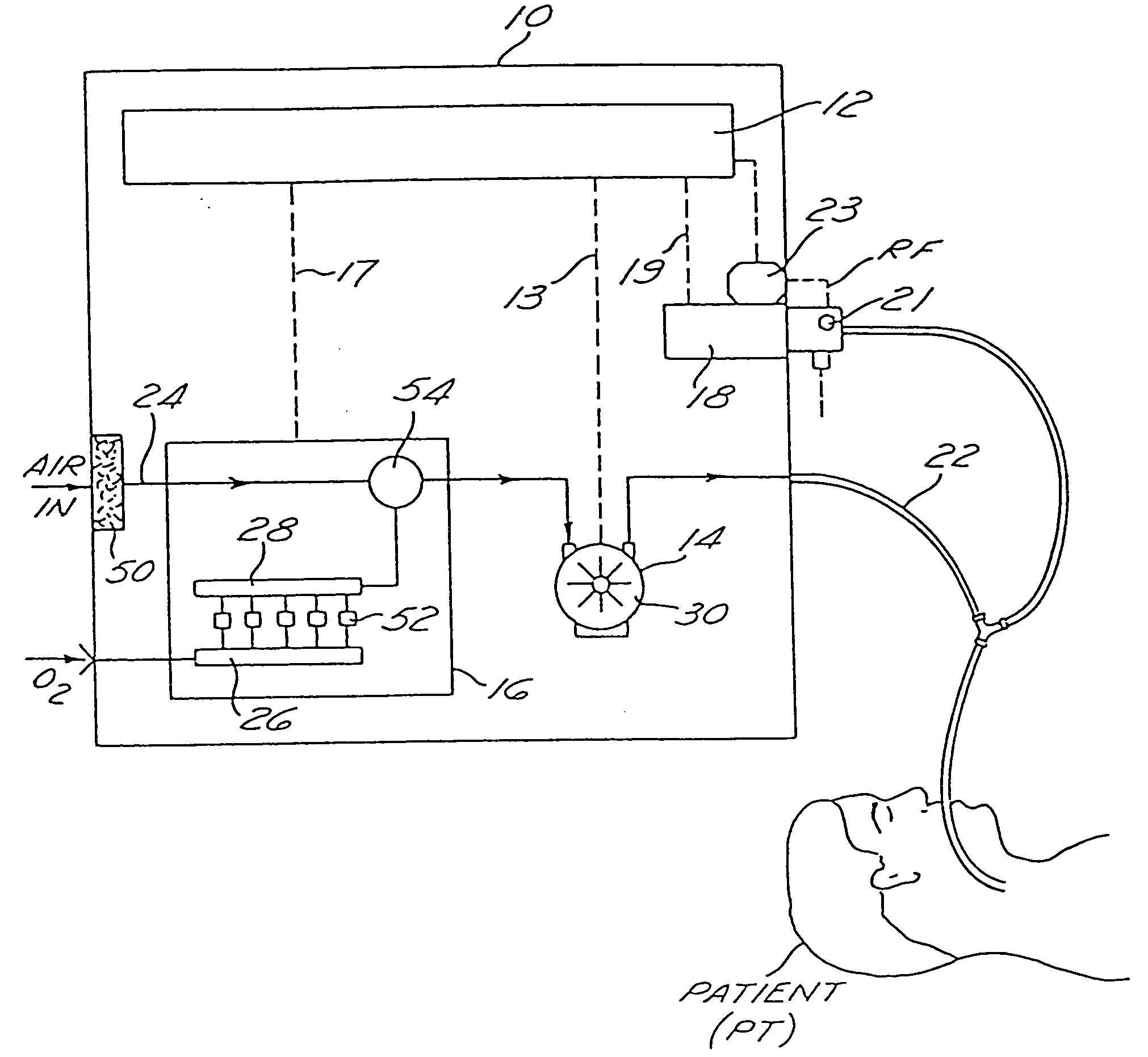
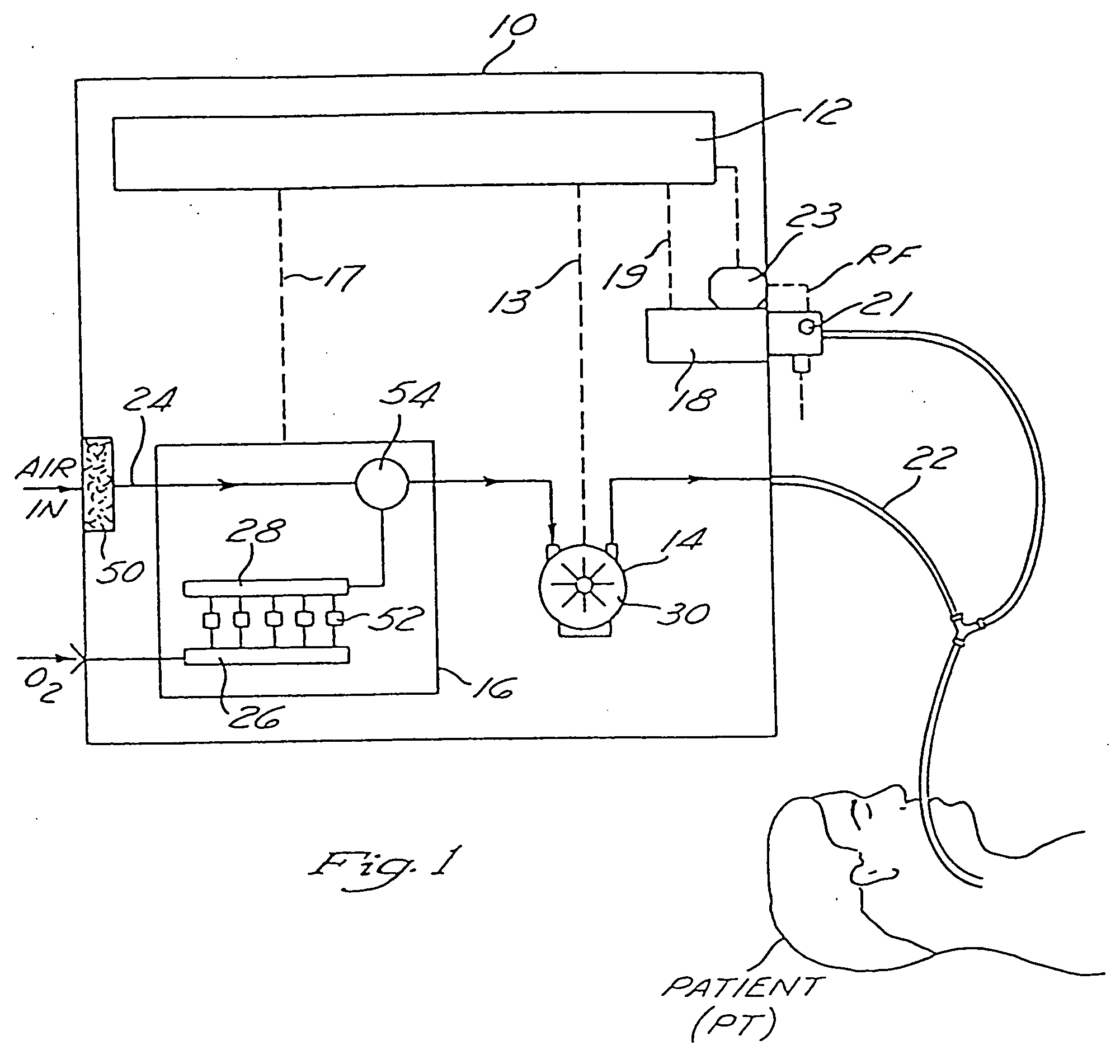
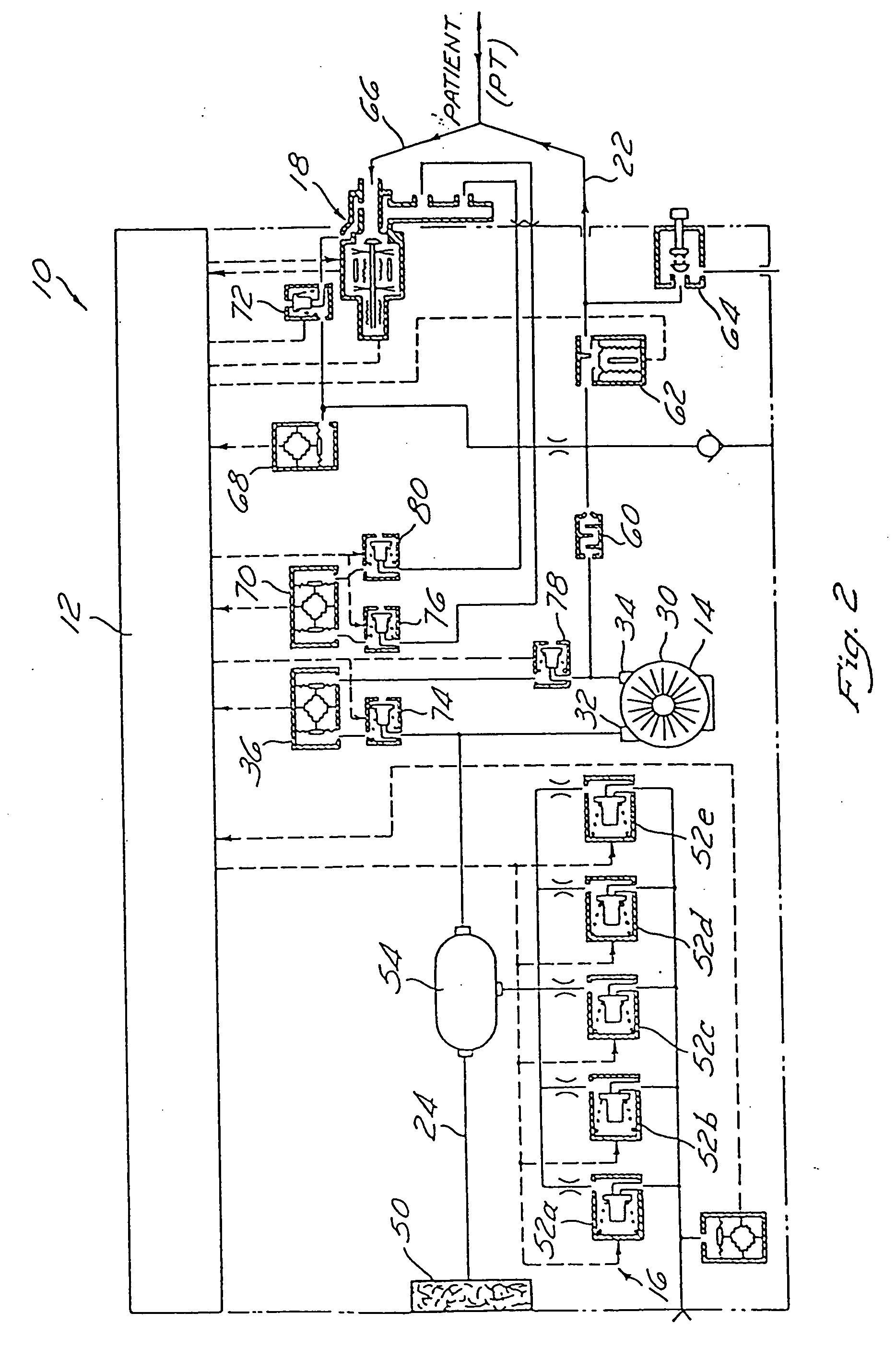
[0086] With reference to FIGS. 1-2, the mechanical ventilation system 10 of the present invention generally comprises a) a programmable microprocessor controller 12, b) a ventilator device 14, c) an optional oxygen blending apparatus 16 and d) an exhalation valve apparatus 18. Which is preferably implemented as a portable, battery powered system.

[0087] The ventilator device 14 incorporates a rotating drag compressor 30 which is driven by an electric motor 102. In response to control signals received...


PUM


Abstract

A ventilator device and system comprising a rotating compressor, preferably a drag compressor, which, at the beginning of each inspiratory ventilation phase, is accelerated to a sufficient speed to deliver the desired inspiratory gas flow, and is subsequently stopped or decelerated to a basal flow level to permit the expiratory ventilation phase to occur. The ventilator device is small and light weight enough to be utilized in portable applications. The ventilator device is power efficient enough to operate for extended periods of time on internal or external batteries. Also provided is an oxygen blending apparatus which utilizes solenoid valves having specific orifice sizes for blending desired amounts of oxygen into the inspiratory gas flow. Also provided is an exhalation valve having an exhalation flow transducer which incorporates a radio frequency data base to provide an attendant controller with specific calibration information for the exhalation flow transducer.

Description

FIELD OF THE INVENTION [0001] The present invention pertains generally to medical equipment and more particularly to a compressor powered mechanical ventilator device for delivering respiratory ventilation to a mammalian patient. BACKGROUND OF THE INVENTION A. Principles of Mechanical Ventilation [0002] In many clinical settings mechanical ventilators are used to facilitate the respiratory flow of gas into and out of the lungs of patients who are sick, injured or anesthetized. [0003] In general, mechanical ventilators provide a repetitive cycling of ventilatory flow, each such repetitive cycle being separated into two phases—an inspiratory phase followed by an expiratory phase. [0004] The inspiratory phase of the ventilator cycle is characterized by the movement of positive-pressure inspiratory flow of gas through the ventilator circuit and into the lungs of the patient. The expiratory phase of the ventilatory cycle is characterized by cessation of the positive pressure inspiratory ...

Claims


Application Information

Patent Timeline
Patent Type & Authority Applications(United States)
IPC IPC(8): A61M16/00A61M16/10A62B7/00A61M16/12A61M16/20F04B49/06F16K1/08G01F1/40G01F1/42
CPCA61M16/00A61M16/206A61M16/0057A61M16/12A61M16/20A61M16/208A61M2016/0021A61M2016/0027A61M2016/0036A61M2016/0039A61M2016/0042A61M2202/0208A61M2205/16A61M2205/18A61M2205/3331A61M2205/3365A61M2205/3561A61M2205/3569A61M2205/3592A61M2205/42A61M2205/502A61M2205/581A61M2205/587A61M2205/70A61M2205/8212G01F1/40G01F1/42A61M16/0063A61M16/0069A61M16/1015A61M16/125A61M16/202A61M16/205A61M16/0051A61M2205/8206A61M2230/46A61M16/107A61M16/0833A61M16/209A61M16/024
Inventor DEVRIES, DOUGLAS F.CEGIELSKI, MICHAEL J.GRAVES, WARNER V. JR.WILLIAMS, MALCOLM R.HOLMES, MICHAEL B.
Owner BIRD PRODS
Why Eureka
Try Eureka