Electromagnetic brake and drive force distributing apparatus for vehicle using the electromagetic brake

a technology of electromagnetism and drive force, which is applied in the direction of braking systems, braking systems, transportation and packaging, etc., can solve the problems of catching one of the right and left wheels, affecting the operation of the vehicle, and the force of the armature being attracted, so as to achieve accurate control of the generated engaging force and accurate positioning

Inactive Publication Date: 2005-06-02
HONDA MOTOR CO LTD
View PDF17 Cites 0 Cited by
  • Summary
  • Abstract
  • Description
  • Claims
  • Application Information

AI Technical Summary

Benefits of technology

[0008] It is therefore an object of the present invention to provide an electromagnetic brake which can achieve accurate positioning between an armature and a core member in the radial direction and can accurately control an engaging force generated in a multiplate brake mechanism.
[0009] It is another object of the present invention to provide a drive force distributing apparatus for a vehicle including the above electromagnetic brake which can arbitrarily distribute a drive force between right and left drive wheels of the vehicle.
[0011] With this configuration, accurate positioning between the armature member and the core member in the radial direction can be achieved by the cylindrical pressure member. Further, since the cylindrical pressure member is fixed to the armature member, inclination of the armature member with respect to the axial direction can be prevented, and a gap defined between the armature member and the core member can be accurately uniformed in the radial direction, thereby allowing accurate control of an engaging force generated in the multiplate brake mechanism. Accordingly, a braking function can be achieved without direct metallic contact, and an attraction force between the core member and the armature member can be efficiently transmitted to the multiplate brake mechanism. Further, the rigidity of the components of the electromagnetic brake in relation to the transmission of the attraction force is considered to minimize the elastic deformation of these components, thereby reducing the hysteresis and stably generating the attraction force.
[0012] Preferably, said core member has a plurality of fastening portions adapted to be fastened to said fixed housing, said fastening portions projecting radially outward from the outer circumference surface of said core member, and said pressure member has a plurality of cutouts for allowing insertion of said fastening portions of said core member. With this configuration, accurate positioning of the core member in the radial and axial directions with respect to the fixed housing can be achieved by the fastening portions. Furthermore, by forming the cutouts in the cylindrical pressure member, the pressure member fixed to the armature member can be fastened to the fixed housing in the condition where the pressure member is fitted with the core by inserting the fastening portions of the core member into the cutouts of the pressure member. Thus, the assembly of the electromagnetic brake can be easily performed.
[0014] Further, the projections for ensuring the accuracy of alignment of the pressure member are formed on a part of the inner circumferential surface of the pressure member rather than the whole thereof, thereby allowing simplification of the structure and a reduction in friction during axial movement of the pressure member. Further, since the pressure member is provided so as to surround the outer circumferential surface of the core member, the second end of the pressure member can press the brake plates and the brake discs of the multiplate brake mechanism at a substantially central position in the effective radius. Accordingly, a uniform pressing force can be applied to the brake plates and the brake discs of the multiplate brake mechanism.

Problems solved by technology

While the primary role of the differential is to obtain smooth cornering as mentioned above, there is a case that one of the right and left wheels may be caught to slip in a muddy place during rough-road running.
As a result, there is a problem that the slipping wheel cannot escape from the muddy place for lack of the drive force for driving the wheels.
This is a problem in a defect inherent in a general differential.
Accordingly, in the case that any of these bars are inclined to the pressure plate, there is a problem that a pressing force of the armature attracted by the solenoid to press the pressure plate of the multiplate clutch may not be uniformly transmitted to the pressure plate.
Accordingly, it is difficult that the conventional structure described in the above publication such that the multiplate clutch is operatively connected to the armature at its inner circumferential portion is applied to the multiplate brake structure without any changes.

Method used


Image

  • Electromagnetic brake and drive force distributing apparatus for vehicle using the electromagetic brake
  • Electromagnetic brake and drive force distributing apparatus for vehicle using the electromagetic brake
  • Electromagnetic brake and drive force distributing apparatus for vehicle using the electromagetic brake

Examples


Embodiment Construction

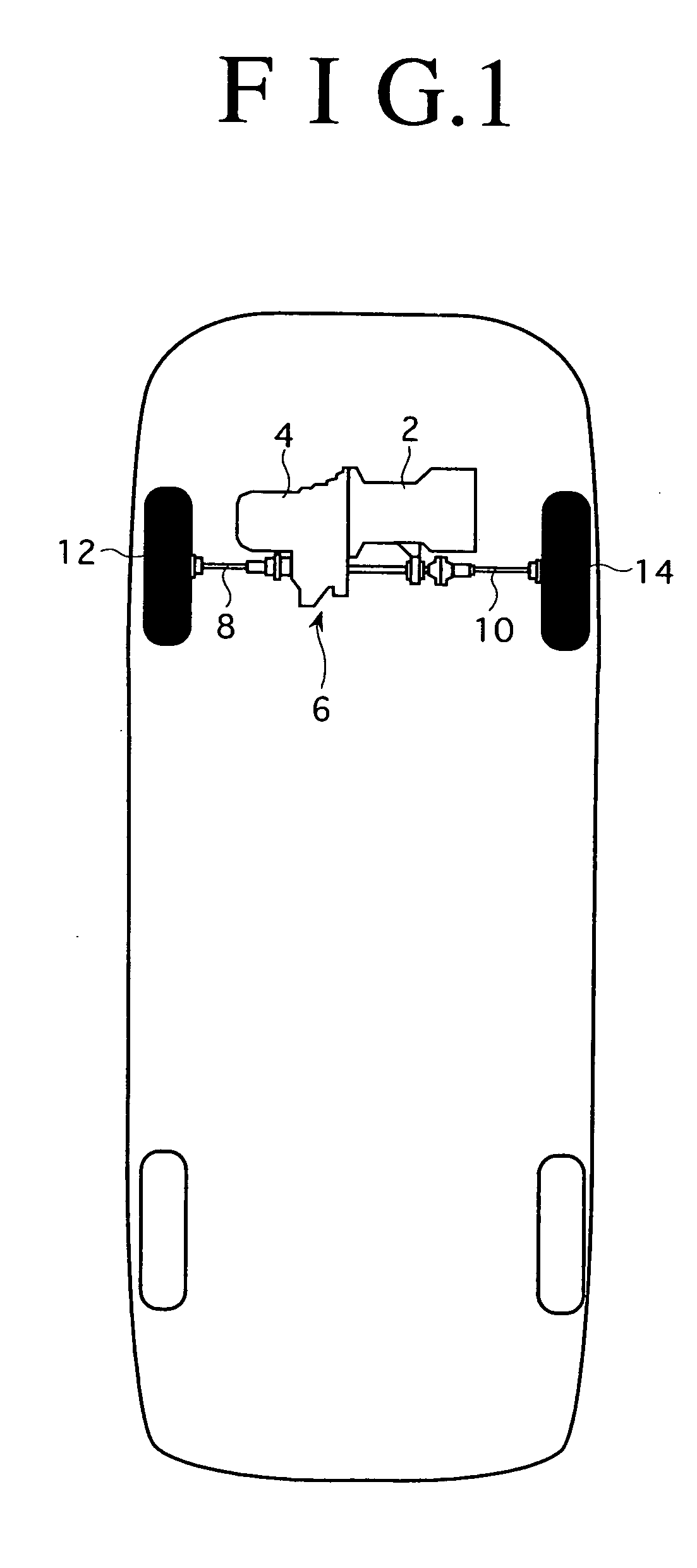
[0033] A preferred embodiment of the present invention will now be described in detail with reference to the drawings. FIG. 1 is a schematic plan view showing the configuration of a front-engine front-drive (FF) vehicle to which a drive force distributing apparatus 6 having the electromagnetic brake of the present invention is applied. A drive force from an engine 2 is transmitted through a transmission 4 to the drive force distributing apparatus 6. The drive force transmitted is distributed between a left front axle 8 and a right front axle 10 by the drive force distributing apparatus 6. The drive force thus distributed drives a left front wheel 12 mounted on the left front axle 8 and a right front wheel 14 mounted on the right front axle 10.

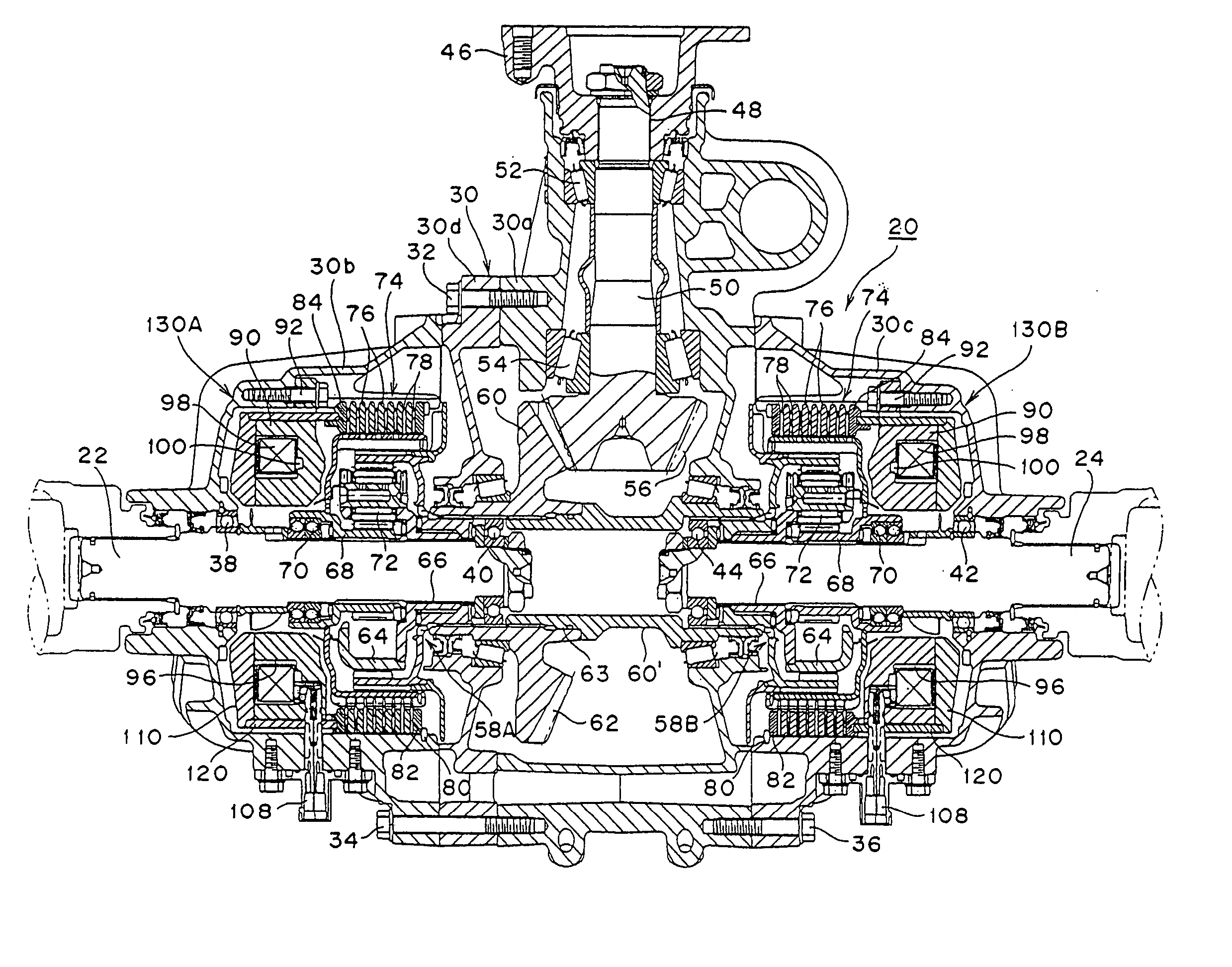
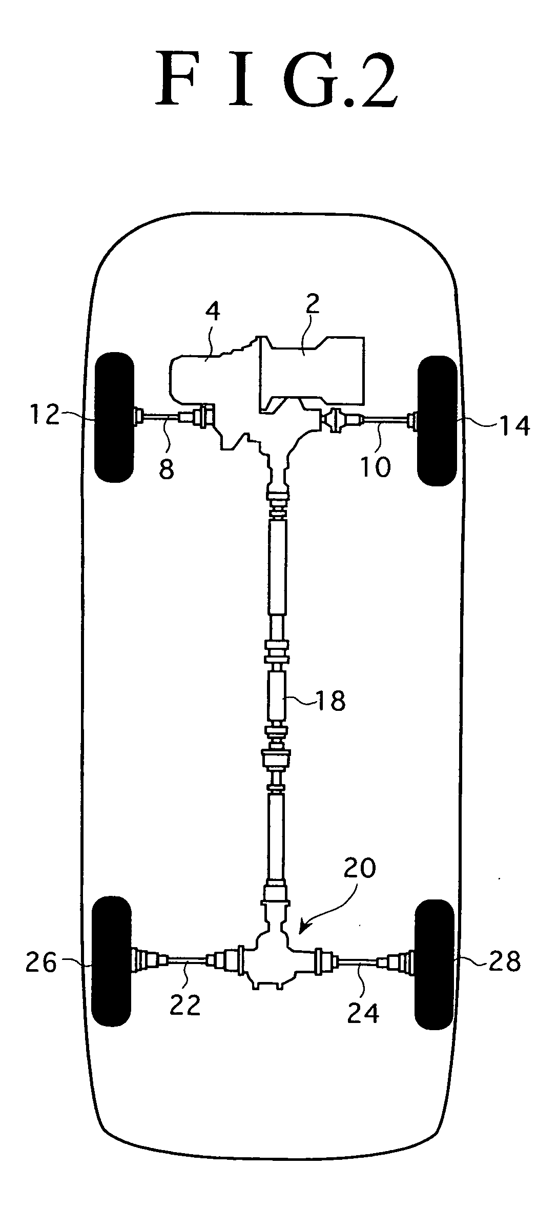
[0034]FIG. 2 is a schematic plan view showing the configuration of a four-wheel drive vehicle to which a drive force distributing apparatus 20 having the electromagnetic brake of the present invention is applied. A drive force from an engine 2...


PUM


Abstract

An electromagnetic brake interposed between a fixed housing and a rotating member. The electromagnetic brake includes a multiplate brake mechanism, a ringlike core member fixed in the fixed housing, an annular exciting coil accommodated in an annular groove formed on the core member, and a ringlike armature member opposed to the annular groove of the core member and having an outer diameter larger than the outer diameter of the core member. The electromagnetic brake further includes an annular pressure plate axially and movably mounted on the fixed housing at one end portion of the multiplate brake mechanism adjacent to the core member, and a cylindrical pressure member provided so as to surround the outer circumferential surface of the core member and be movable in a direction of pressing the multiplate brake mechanism as being guided by the core member. One end of the cylindrical pressure member is fixed to an outer circumferential portion of the armature member, and the other end is engaged with the annular pressure plate.

Description

BACKGROUND OF THE INVENTION [0001] 1. Field of the Invention [0002] The present invention relates to an electromagnetic brake and a drive force distributing apparatus for a vehicle using the electromagnetic brake. [0003] 2. Description of the Related Art [0004] A differential is located in a power train of a vehicle to maintain torque distribution between right and left wheels of the vehicle such that torque is equally divided between the right and left wheels and to rotate the outside wheel faster than the inside wheel during cornering, thereby reliably obtain smooth cornering. While the primary role of the differential is to obtain smooth cornering as mentioned above, there is a case that one of the right and left wheels may be caught to slip in a muddy place during rough-road running. [0005] In this case, the resistance from the road to the wheel caught to slip in the muddy place is small, so that torque is almost transmitted to this slipping wheel and hardly transmitted to the o...

Claims


Application Information

Patent Timeline
Patent Type & Authority Applications(United States)
IPC IPC(8): F16D27/08B60K17/16B60K23/04B60L7/00B60T1/06B60T13/74F16D27/108F16D27/112F16D27/115F16D55/36F16D65/14F16H48/12
CPCB60K17/16B60K23/04B60T1/062F16D55/36F16H2048/423F16H48/12F16H48/19F16H48/34F16H2048/346F16D2121/20
Inventor IWAZAKI, AKIHIROKUNII, RIKIYA
Owner HONDA MOTOR CO LTD
Why Eureka
Try Eureka