
Support device

a technology of support and support plate, which is applied in the direction of mould fastening means, domestic objects, shaping building parts, etc., can solve the problems of affecting the quality of the panel, so as to reduce the likelihood of damage to the formwork surface and facilitate the adjustment

Inactive Publication Date: 2005-06-02
RETAIL & COMML PROPERTIES PTY
View PDF11 Cites 28 Cited by
  • Summary
  • Abstract
  • Description
  • Claims
  • Application Information

AI Technical Summary

Benefits of technology

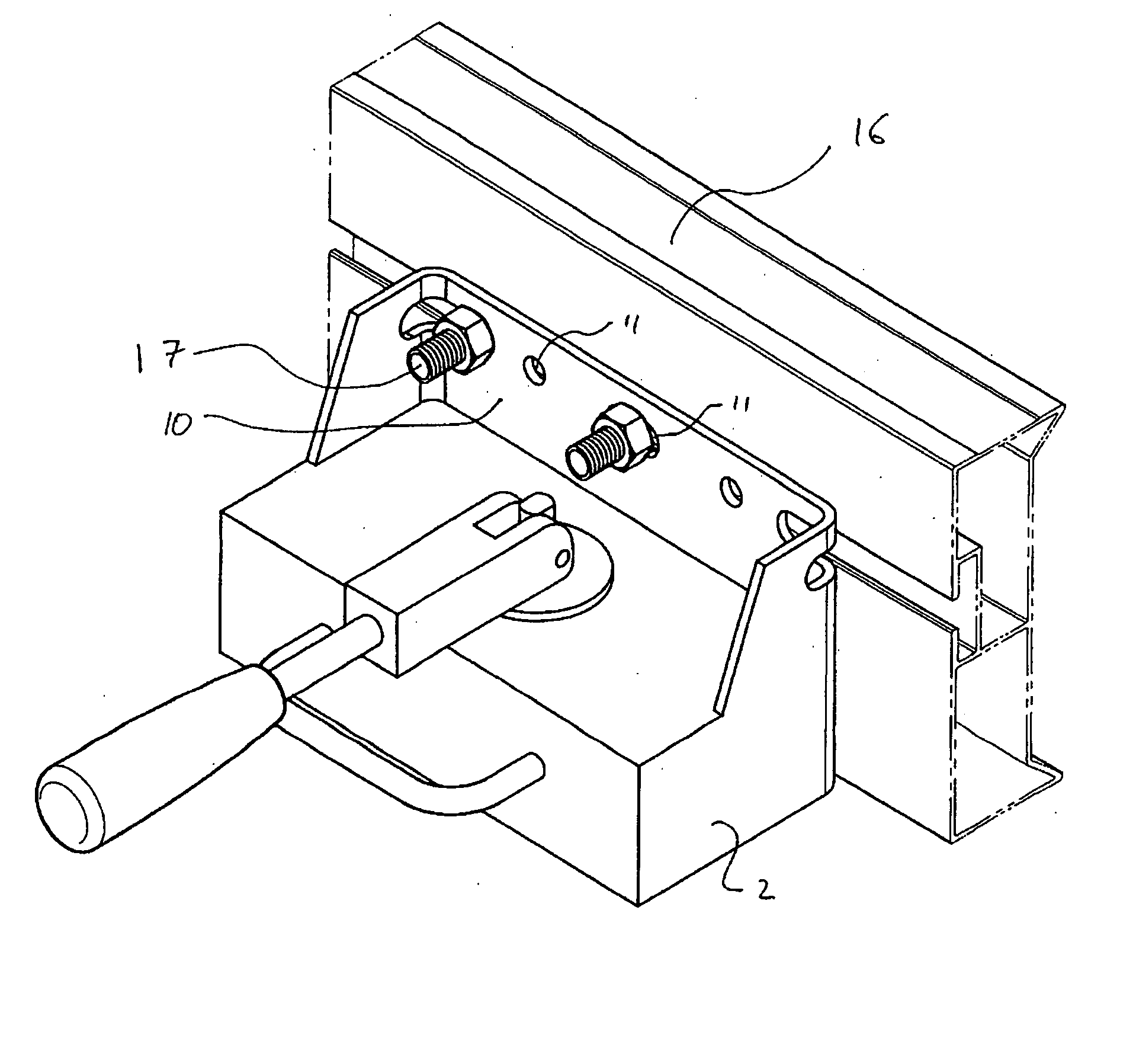
[0017] The support structure preferably includes means for facilitating connection of the support structure to the formwork member. This means may be in the form of a flange provided with at least one aperture to receive a fastening means, for fastening the formwork member to the flange. Preferably, in use the flange extends in a direction transverse to the formwork surface. Alternatively, in use the flange extends in a direction substantially perpendicular to the formwork surface. Preferably, the at least one aperture existing through the flange is adapted to facilitate adjustment of the fastening means relative to the support device and the formwork member. Preferably, the at least one aperture is adapted to facilitate lateral and longitudinal adjustment of the fastening means relative to the flange. More preferably, this angle is about 45 degrees relative to the formwork surface when the support device is in use. This allows for variations in the formwork surface to be compensated when connecting the support device to the formwork member.
[0021] In at least one preferred embodiment, the non-engaging side includes an adjustable height means for adjusting the height of the non-engaging side of the support structure, relative to the engaging side of the support structure. Preferably, the adjustable height means includes a plate extending from a non-engaging side; at least one shank extending from the plate towards the formwork surface; and at least one complimentary foot, each foot being adjustable along each shank. Preferably, the shank and foot have complimentary threads to make adjustment easier. Preferably, each foot includes an outer surface that is flexible / elastic, so that in the operating condition, the foot reduces the likelihood of damaging the formwork surface.
[0022] Preferably, adjustment of the foot allows the angle of the formwork member to be adjusted relative to the formwork surface. In one form, only one non-engaging side having the adjustable height means is included and located on the side opposite the engaging face. This allows for rotation of the support structure in a direction toward the formwork member. Alternatively, all the other sides of support structure have non-engaging sides having the adjustable height means. This allows for the sides adjacent the engaging side to be raised higher than the side opposite the engaging side, allowing for rotation of the support structure in a direction away from the formwork member.

Problems solved by technology

This style of support is time consuming to install and dismantle once the panel has cured.
Furthermore the formwork surface is generally damaged when the support is removed.
It should be appreciated that where any subsequent panel is of greater dimension than previous panels the wet concrete will be poured onto the damaged formwork surface, and as such will produce a panel of inferior surface quality.
Alternatively the formwork surface will have to be repaired which further adds to the costs.
Mechanisms have been designed to facilitate detaching the magnet from the formwork surface, however they tend to be over technical in their design with excessive moving parts, which mechanisms are not entirely suitable for the corrosive environment of construction.
Furthermore, the mechanisms tend to include resilient means for counteracting any magnetic attractive force, and given that the relative strength of both the resilient means and the magnetic force tends to alter over the life of the magnet or resilient means, this can tend to produce a support device which may perform unpredictably.

Method used


Image

  • Support device
  • Support device
  • Support device

Examples


Embodiment Construction

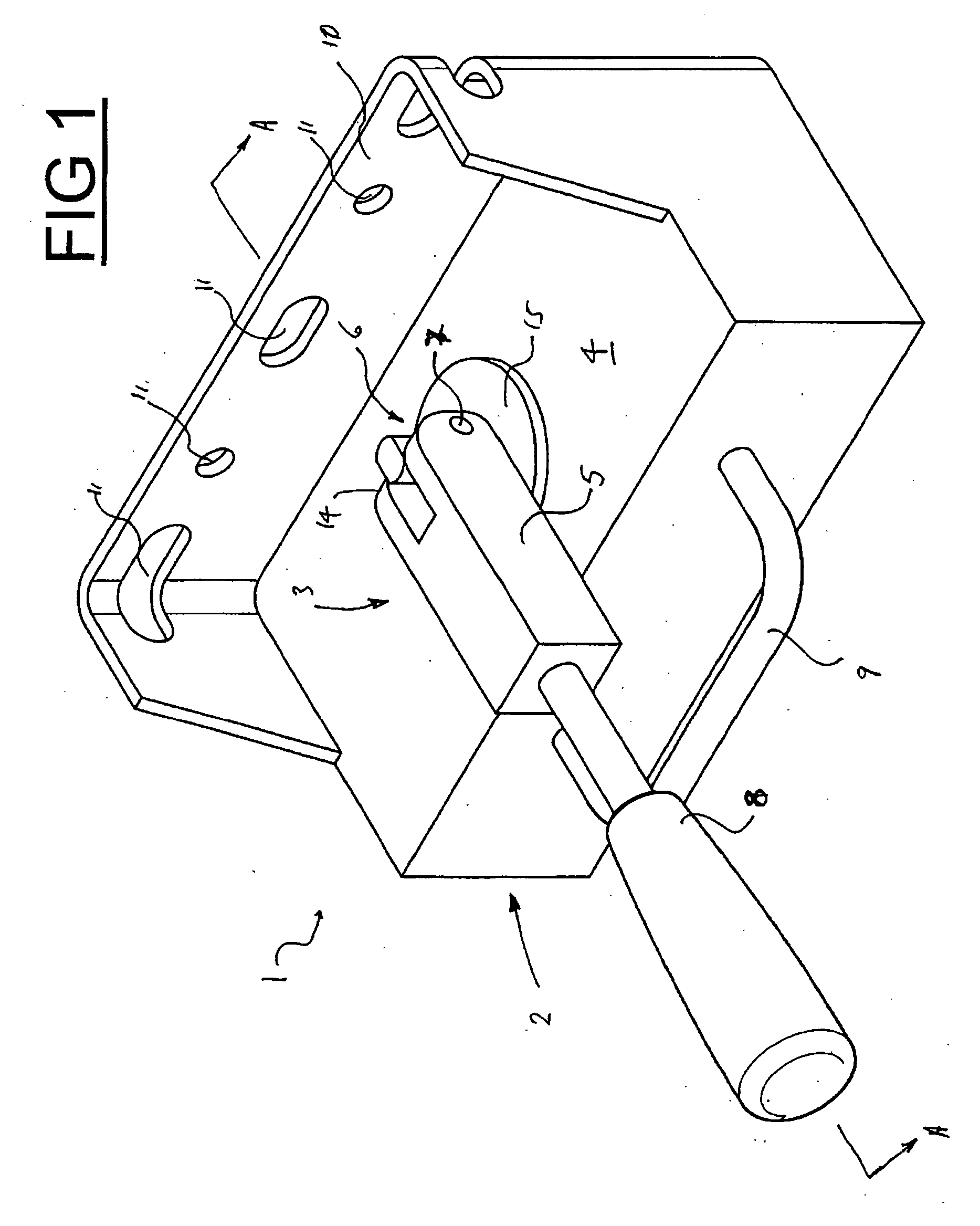
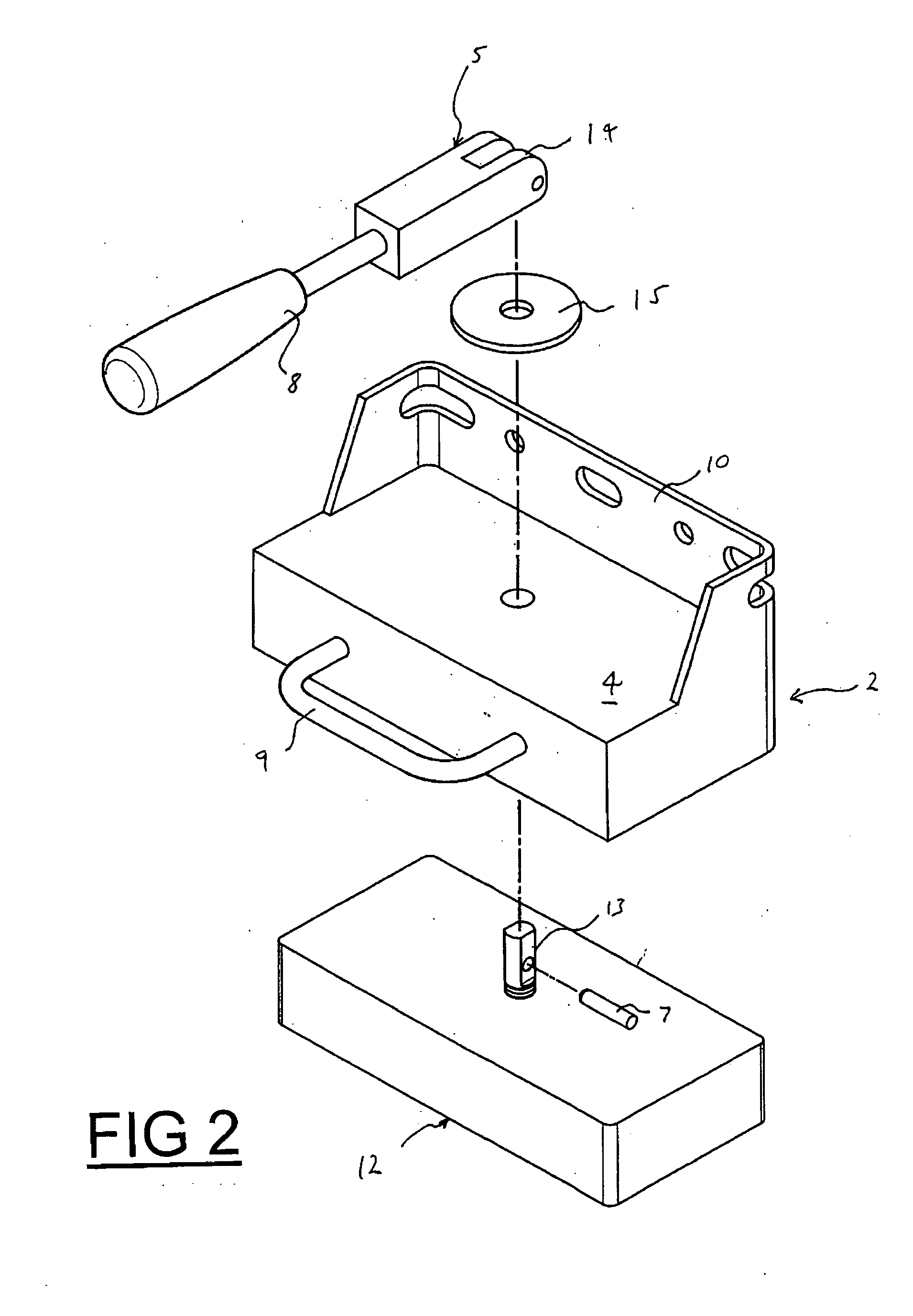
[0039] Referring now to FIG. 1 there is illustrated a preferred form of a support device 1 according to the invention. The support device 1 illustrated includes a support structure 2 with a switching means 3 located adjacent an upper surface 4 of the structure 2. The switching means 3 illustrated includes a cam member 5 connected to a link member 6 via a pin 7. The switching member 3 illustrated also includes a lever 8 extending from an end of the cam member 5 for facilitating operation of the switching means 3, which operation will be discussed later on in the specification.

[0040] The support structure 2 also includes a handle 9 for facilitating manipulation of the support device 1, which handle 9 extends from a surface of the structure extending substantially transverse to the upper surface 4. Clearly the location of the handle 9 is merely preferred and it is possible that the handle 9 may be located on an alternative position of the structure 2.

[0041] The structure 2 illustrate...


PUM


Abstract

This invention relates to a device for providing temporary support to a structure such as a formwork member. The invention includes a support device (1) for supporting a formwork member (16) adjacent to formwork surface. A securing means (12) is associated with the structure being operable for securing the support device to the formwork surface. A switching means (3) is provided for switching the securing means (12) between an operating condition whereby the securing means (12) secures the support device to the formwork surface, and a non operating condition whereby the securing means (12) is not securing the support device to the formwork surface. Advantageously, the support device (1) can be easily and predictably activated and de-activated.

Description

FIELD OF THE INVENTION [0001] This invention relates to a device for providing temporary support to a structure. The device is particularly, but not exclusively, suited to temporary support of a formwork structure. The device has a particular application in the concrete construction industry and it will be convenient to hereinafter describe the invention in relation to this particular application. It should be appreciated however that the device has wider application. BACKGROUND TO THE INVENTION [0002] A popular form of concrete construction includes horizontally pre-casting of panels which after curing are subsequently “tilted up” into position. The panels are generally cast on a formwork surface. It should be appreciated that the quality of the surface finish of the panel is dictated by the quality of the surface on which it is cast. In this regard the formwork surface may be formed from smooth timber, metal or cured concrete. [0003] The length, width and depth of the panel is def...

Claims


Application Information

Patent Timeline
IPC IPC(8): B28B7/00F16M13/00
CPCB28B7/002B28B7/0017
Inventor SAMUEL, MICHAEL
Owner RETAIL & COMML PROPERTIES PTY
Learn More