
Digital camera capable of obtaining crop image

Inactive Publication Date: 2005-06-02
NIKON CORP
View PDF6 Cites 47 Cited by
  • Summary
  • Abstract
  • Description
  • Claims
  • Application Information

AI Technical Summary

Benefits of technology

[0010] An object of the present invention is to allow a crop image of a subject to be easily obtained.
[0011] Another object of the present invention is to shorten the time necessary after a subject is photographed in motion photography until a desired image is cut out from the photographed image.

Problems solved by technology

Thus, when the photographer photographs a speedy subject such as sports players or children who are moving around, the photographer may miss a shutter chance.
In other words, when the photographer performs motion photography, it is difficult and impractical for the photographer to set a crop area in addition to various setting items such as a focus setting.
When the photographer performs motion photography at a news spot or the like, it is difficult for the photographer to use the crop function.
However, when the post-photographed image process is performed, it takes a long time after a desired image is cut out from an image of a subject until the cutout image is reported or inserted.

Method used


Image

  • Digital camera capable of obtaining crop image
  • Digital camera capable of obtaining crop image
  • Digital camera capable of obtaining crop image

Examples


first embodiment

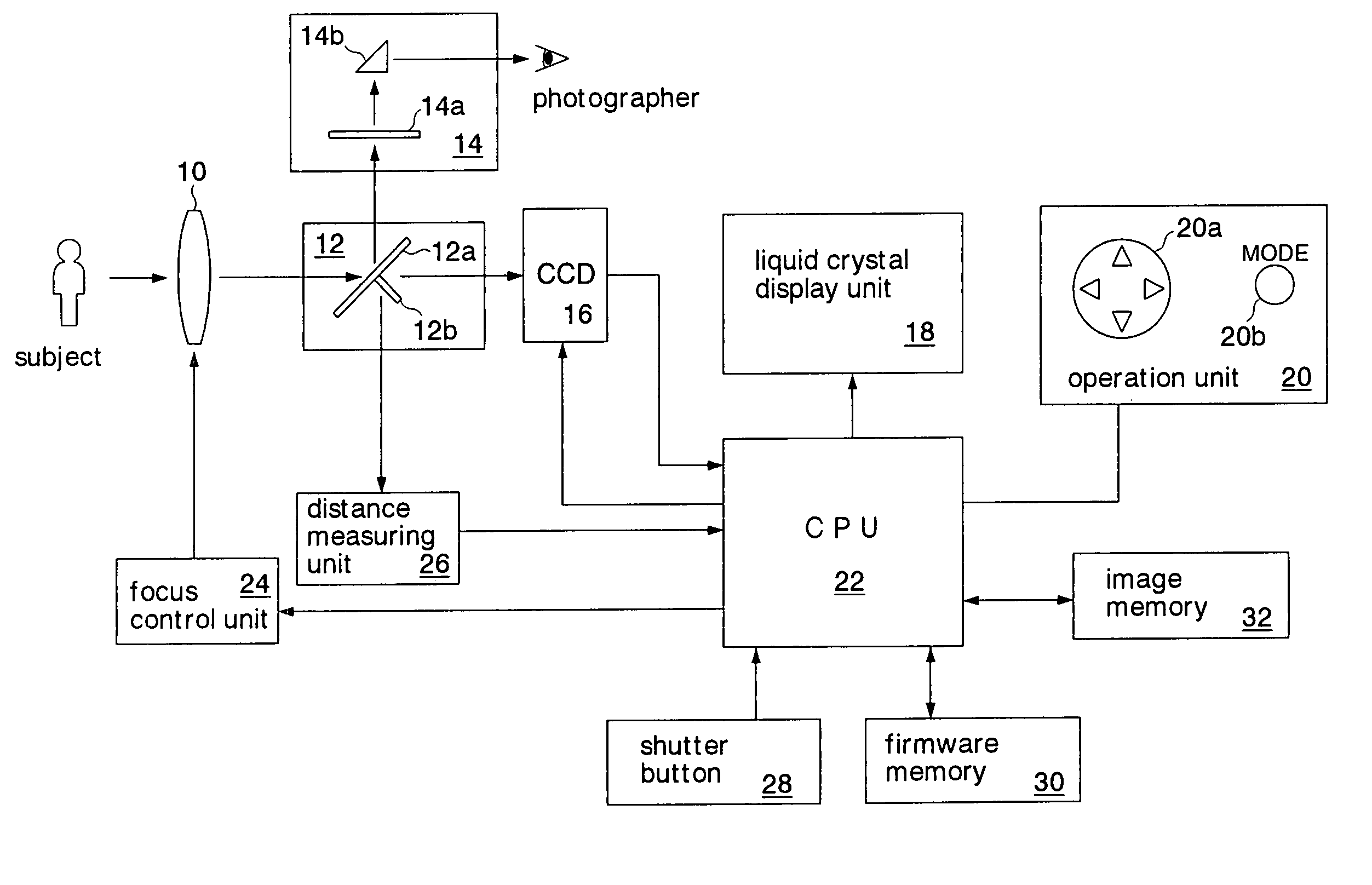
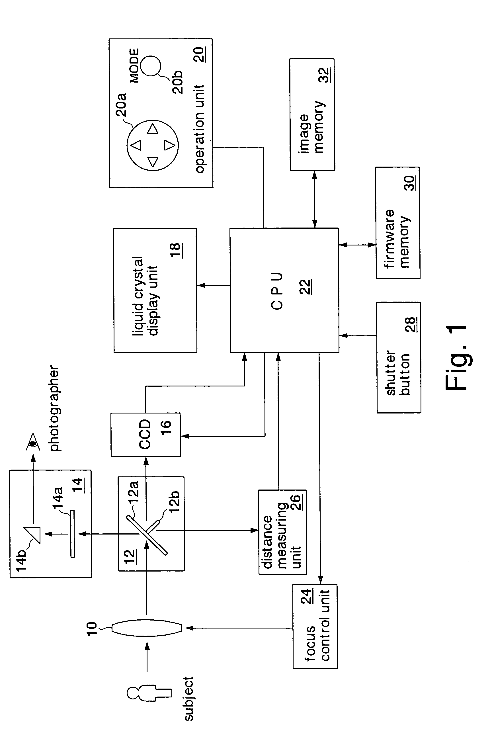
[0043]FIG. 1 shows a digital camera according to a first embodiment of the present invention. The digital camera is a single lens reflex camera. The digital camera includes an exchangeable lens 10, a mirror unit 12, a view finder 14 (display section), a charge coupled device (CCD) 16 (imaging section), a liquid crystal display unit 18, an operation unit 20, a CPU 22, a focus control unit 24, a distance measuring unit 26, a shutter button 28, a firmware memory 30, and an image memory 32 (image memory).

[0044] In reality, the exchangeable lens 10 is composed of a plurality of lenses including a focus lens with which a subject is focused and a zoom lens with which the subject is zoomed. The mirror unit 12 has a mirror 12a that reflects rays of light emitted from a subject to the view finder 14 and a mirror 12b that reflects the rays of light emitted from the subject to the distance measuring unit 26. The mirror unit 12 is interposed between the exchangeable lens 10 and the CCD 16 so th...

second embodiment

[0081]FIG. 10 shows a digital camera according to a second embodiment of the present invention. In FIG. 10, the same elements as those described in the first embodiment are denoted by the reference numerals and their detailed description will be omitted. The digital camera according to the second embodiment is a so-called compact digital camera. The digital camera includes a lens 40, a CCD 46 (imaging section), a liquid crystal display unit 48, an operation unit 50, a CPU 52, a focus control unit 54, a shutter button 58, a firmware memory 60, and an image memory 62 (image memory). The functions of these elements are almost the same as the functions of the elements of the first embodiment except that a pre-photographed image of a subject is displayed in the liquid crystal display unit 48. Since the digital camera uses a contrast detecting system of which a subject is focused in accordance with the state of the contrast of an image formed by the CCD 46, the function of a distance meas...

third embodiment

[0087]FIG. 12 shows a screen displayed on a liquid crystal display unit in the case that a photography mode is set in a digital camera according to a third embodiment of the present invention. In FIG. 12, the same elements as those in the first embodiment are denoted by the same reference numerals and their detailed description will be omitted. The structure of the third embodiment is the same as the structure of the first embodiment except for the program that the CPU 22 shown in FIG. 1 executes and that is stored in the firmware memory 30. In other words, the digital camera according to the third embodiment is a single lens reflex digital camera.

[0088] The screen shown in FIG. 12 is displayed when the photographer selects the photography mode in FIG. 6. On the screen, by pressing the upper triangle mark or lower triangle mark of the cross button 20a shown in FIG. 1, the photographer selects one of a normal photography mode, a crop photography mode, and a crop & full screen photog...


PUM


Abstract

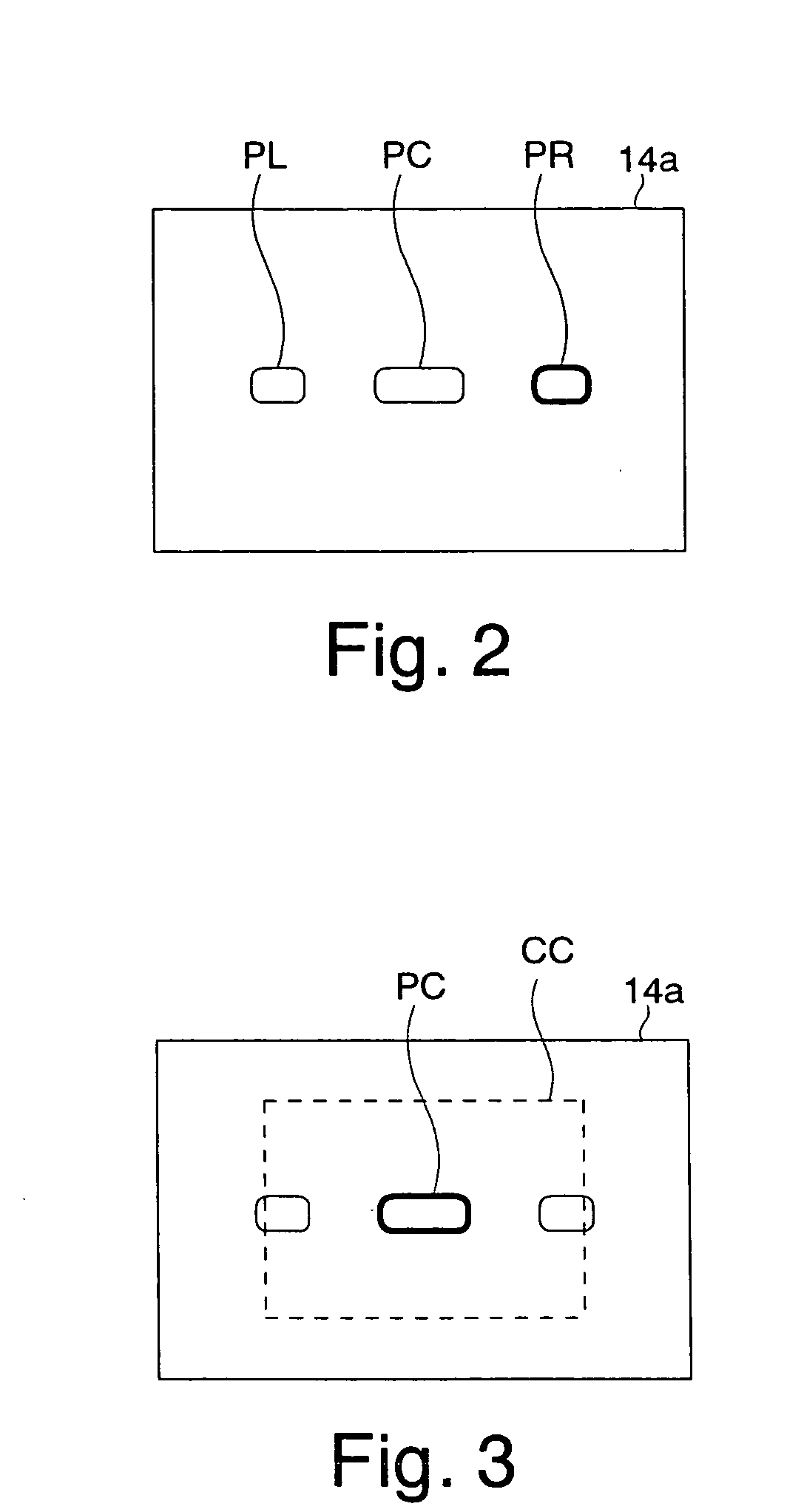
An imaging section inputs rays of light from a subject through a lens and forms an image of the subject. A display screen of a display section displays an image of a subject focused by the lens. A focus area selecting section selects one of a plurality of focus areas displayed on the display screen. A focus adjusting section adjusts a focus on the subject in the selected focus area. A crop section automatically selects a crop area corresponding to the selected focus area and captures as a crop image an image in the selected crop area. The photographer can easily obtain a crop image by photographing a subject according to a conventional procedure.

Description

CROSS-REFERENCE TO RELATED APPLICATIONS [0001] This application is based upon and claims the benefit of priority from Japanese Patent Application No. 2003-397458, filed on Nov. 27, 2003, the entire contents of which are incorporated herein by reference. BACKGROUND OF THE INVENTION [0002] 1. Field of the Invention [0003] The present invention relates to a digital camera having a function for cropping a part of an image formed by an imaging device. [0004] 2. Description of the Related Art [0005] The number of pixels of imaging devices used in digital cameras is being increased year after year. As a result, precise images and clearly enlarged prints can be obtained. A news photo that is inserted in a newspaper, a magazine, or the like is often created by cropping (cutting out) a part of an original image and enlarging the cropped image. When an image that has been formed is cropped, it needs a process time (edit time). Thus, for a news photo whose edit time necessary after it is photog...

Claims


Application Information

Patent Timeline
IPC IPC(8): H04N5/225H04N5/232H04N5/262
CPCH04N5/23212H04N5/2628H04N5/23293H04N5/23245H04N23/673H04N23/667H04N23/635
Inventor SUZUKI, HIROBUMI
Owner NIKON CORP
Learn More