Liquid crystal display device and method of fabricating the same

a liquid crystal display and liquid crystal technology, applied in optics, instruments, electrical equipment, etc., can solve the problems of severe deformation of black picture state, rubbing defect caused by even larger step difference, etc., and achieve the effect of improving aperture ratio and image quality

Active Publication Date: 2005-06-02
LG DISPLAY CO LTD
View PDF2 Cites 31 Cited by
  • Summary
  • Abstract
  • Description
  • Claims
  • Application Information

AI Technical Summary

Benefits of technology

[0018] An object of the present invention is to provide an LCD device having an improved aperture ratio.
[0019] Another object of the present invention is to provide an LCD device having an image quality by preventing a rubbing defect that causes light leakage.
[0020] Another object of the present invention is to provide a method of fabricating the LCD device to prevent a rubbing defect that causes light leakage.

Problems solved by technology

This light leakage severely degrades a black picture state.
Thus, a rubbing defect caused by an even larger step difference becomes more severe.

Method used


Image

  • Liquid crystal display device and method of fabricating the same
  • Liquid crystal display device and method of fabricating the same
  • Liquid crystal display device and method of fabricating the same

Examples


Embodiment Construction

[0036] Reference will now be made in detail to the preferred embodiments of the present invention, examples of which are illustrated in the accompanying drawings. Wherever possible, the same reference numbers will be used throughout the drawings to refer to the same or the like parts.

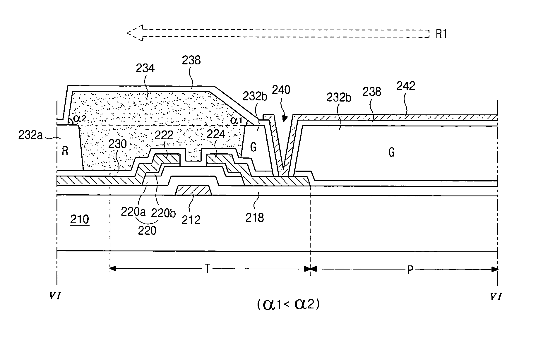
[0037]FIGS. 4A and 4B are schematic views showing a liquid crystal display device according to an embodiment of the present invention. FIG. 4A is a plan view and FIG. 4B is a cross-sectional view taken along a line IV-IV of FIG. 4A.

[0038] As shown in FIG. 4A, a plurality of pixel regions P are defined on a substrate 110. A black matrix 114 is formed on the substrate 110 and has a plurality of open portions 112. Each of the open portions 112 corresponds to each of the pixel regions P. The black matrix 114 is formed from resin materials including at least one of carbon particles, titanium oxide (TiOx) and color pigments.

[0039] A color filter layer 116 is formed over the black matrix 114 on the substrat...


PUM

PropertyMeasurementUnit
internal acute angleaaaaaaaaaa
angleaaaaaaaaaa
internal acute angle α2aaaaaaaaaa

Abstract

A liquid crystal display device include: a first substrate and a second substrate facing each other, the first and second substrate including pixel regions; a first alignment layer on the first substrate; a black matrix on the second substrate; a first sloped side of the black matrix that is less steep than a second sloped side of the black matrix; a color filter layer on the black matrix; a second alignment layer on the color filter layer; a liquid crystal material interposed between the first and second alignment layers; and a rubbing direction of the second alignment layer corresponding to a first direction from the first sloped side to the second sloped side.

Description

[0001] This application claims the benefit of Korean Patent Application No. 2003-86362, filed on Dec. 01, 2003, which is hereby incorporated by reference. BACKGROUND OF THE INVENTION [0002] 1. Field of the Invention [0003] The present invention relates to a liquid crystal display (LCD) device, and more particularly, to an LCD device and a method of fabricating the LCD device. [0004] 2. Description of the Related Art [0005] Presently, LCD devices are being developed as the next generation of display devices because of their light weight, thin profile, and low power consumption. In general, an LCD device is a non-emissive display device that displays images using a refractive index difference utilizing optical anisotropy properties of a liquid crystal material that is interposed between an array (TFT) substrate and a color filter substrate. Among the various type of LCD devices commonly used, active matrix LCD (AM-LCD) devices have been developed because of their high resolution and s...

Claims


Application Information

Patent Timeline
Patent Type & Authority Applications(United States)
IPC IPC(8): G02F1/133G02F1/1333G02F1/1335G02F1/1337G02F1/136G02F1/1362H01L21/00H01L29/786
CPCG02F1/133512G02F1/133514G02F2001/136222G02F1/136209G02F1/133784G02F1/136222G02F1/1335
Inventor KIM, WOONG-KWONPARK, SEUNG-RYULL
Owner LG DISPLAY CO LTD
Why Eureka
Try Eureka