3D display apparatus

a display apparatus and 3d technology, applied in the field of 3d display apparatus, can solve the problems of not considering the diffraction of light, certain limits for developing and fabricating optimized 3d products, and giving a viewer a bad feeling to the viewer's eyes, so as to reduce the optical bad feeling, optimize the 3d image, and convert the effect of a common imag

Inactive Publication Date: 2005-06-02
PAVONINE
View PDF6 Cites 34 Cited by
  • Summary
  • Abstract
  • Description
  • Claims
  • Application Information

AI Technical Summary

Benefits of technology

[0027] It is another object of the present invention to provide a 3D image display apparatus capable of decreasing an optical bad feeling due to a Moire pattern by adapting a parallax barrier of which a transparent slit portion of a parallax barrier type is formed in a tooth shape, and capable of obtaining an optimized 3D image by adapting a new formula when computing a pitch of a parallax barrier. In addition, it is possible to easily convert a common image and a 3D image by adapting an electronic shutter and achieving an on and off operation.
[0028] To achieve the above objects, in a 3-dimensional (3D) image display apparatus capable of easily viewing a common image and a 3D image in such a manner that there are provided an image panel, and a parallax barrier of which a transparent slit is formed in a tooth shape wherein an electronic shutter type parallax barrier is fabricated in a shape of the parallax barrier for thereby achieving an on and off operation, wherein a ¼ phase plate is provided between the parallax barrier and the image panel for thereby preventing a change of colors, there is provided a 3D display apparatus that is characterized in that the front polarized film of the image panel is shared, and a TAC film is attached on the image panel for thereby preventing scattering of light from the image panel, and a microsphere layer is coated on the surface of the TAC film for preventing a Newton ring phenomenon, and in the case that the parallax barrier is provided behind the image panel, the pitch of the parallax barrier is S=2Pk(V+D) / V, and in the case that the parallax barrier is provided in front of the image panel, the pitch of the same is S=2Ph(V−D)V where S is a slit pitch in a horizontal direction, and P is a pitch of sub-pixels R and L in a horizontal direction, and V is a distance from the sub-pixels R and L to a viewer, and D is a distance from the sub-pixels R and L to the parallax barrier, and k is a constant value having a range of 0.98<k<1.00, and h is a constant value having a range of 1.00<h<1.02.
[0029] In addition, the transparent slit of the parallax barrier is formed in a tooth shape in order to decrease an optical bad feeling due to a Moire pattern and enhance the performance of a 3D apparatus wherein the angle A in the tooth shape is 10˜15° with respect to a vertical line, and it is symmetrical in the upper and lower directions, and the width of the transparent slit is about ½ of the pitch S, and the pitch of the transparent portion in the upper and lower directions is about ½ of the pitch S in the left and right directions.

Problems solved by technology

However, the method of using the glasses may cause inconveniences.
In addition, there are some problems when viewing other objects except for the 3D image in a state that the glasses are worn.
However, the conventional art may give a viewer a bad feeling to the viewer's eyes since a Newton ring phenomenon occurs.
However, when the Equations (1) and (2) are actually adapted to the products, there is a certain limit for developing and fabricating the optimized 3D products.
Second, the diffraction of light is not considered.
In this case, the ghost is slightly decreased, but the brightness of the 3D image is decreased, and the dark Moire pattern appears in the vertical direction, so that the viewer may have a bad feeling.
In addition, the light intensity distribution in the horizontal direction of the Moire pattern appears in a step shape and a dim rainbow shape, so that the viewer may have a bad feeling.
Therefore, there is a big problem for viewing the 3D image.
Therefore, the viewer may have a bad feeling.

Method used


Image

  • 3D display apparatus
  • 3D display apparatus
  • 3D display apparatus

Examples


Embodiment Construction

[0039] The preferred embodiments of the present invention will be described with reference to the accompanying drawings.

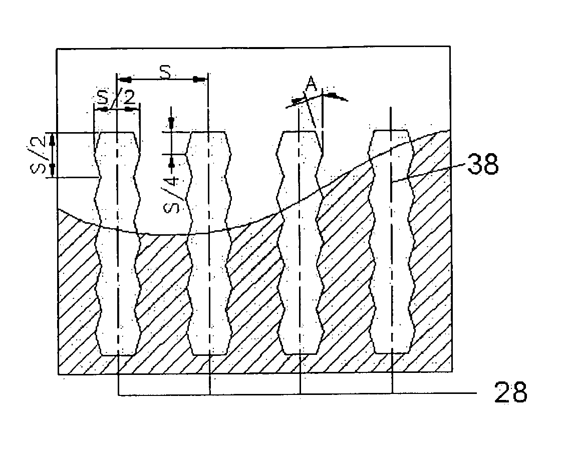
[0040]FIGS. 5A and 5B are views illustrating parallax barrier patterns according to the present invention, and FIG. 6 is a cross sectional view illustrating an assembling of a parallax barrier method according to the present invention.

[0041] As shown in FIG. 5A, it is possible to enhance the light transmittance by over 30% as compared to the conventional art in such a manner that the width of the opening is widened with over 45% of the pitches of two corresponding pixels by improving the conventional opening to have a width below ⅓ of pixels. In addition, the shape of the transparent slit is designed to have the shape of FIG. 4A and the tooth shape like the tooth shaped transparent portions 38 and 39. Here, the transparent portion is designed to have ½ of the pitch S and ½ of the pitch S in the upper and lower directions. The angle A of the tooth shape is slanted...


PUM


Abstract

The present invention relates to a 3D image display apparatus of a parallax barrier method. In the 3D image display apparatus of a parallax barrier method, a parallax barrier of which a transparent slit portion is formed in a tooth shape is adapted, so that it is possible to decrease an optical bad feeling due to Moire pattern. When designing the pitch S of the parallax barrier, in the case that the parallax barrier is disposed behind the image panel the pitch S is S=2Pk(V+D)/V, and in the case that the parallax barrier is disposed in front of the image panel, the pitch S is S=2Ph(V−D)/V. In the 3D image reproducing apparatus according to the present invention, an excellent performance can be achieved as compared to the simple 3D image. The common image can be easily converted into a 3D image using an on and off operation using the electronic shutter.

Description

BACKGROUND OF THE INVENTION [0001] 1. Field of the Invention [0002] The present invention relates to a 3-dimensonal display apparatus, and in particular to a 3D display apparatus and a method for optimizing the same. [0003] 2. Description of the Background Art [0004] Generally, a 3D image capable of expressing 3 dimensions is obtained based on a remote distance of a stereo visibility using two eyes. Since two eyes are distanced by about 65 mm, a difference distance between two eyes is the most important factor in 3D images. [0005] The left and right eyes see different 2D images, respectively. When two images are transferred to a brain through a retina, the brain recognizes the images for thereby reproducing the depth and actuality of a 3D image [0006] In a method for viewing a 3D image, there are a glasses-wearing method and a non-glasses wearing method based on the use of glasses by a viewer. [0007] The method of using glasses may be classified into an anaglyph method in which blue...

Claims


Application Information

Patent Timeline
Patent Type & Authority Applications(United States)
IPC IPC(8): G02B30/30H04N13/00
CPCG02B27/2214H04N13/0411H04N13/0409H04N13/312H04N13/31G02B30/30G02B30/27
Inventor LEE, SUNG-JUNG
Owner PAVONINE
Why Eureka
Try Eureka