Ion generating unit

Inactive Publication Date: 2005-06-02
MATSUSHITA ELECTRIC WORKS LTD
View PDF2 Cites 10 Cited by
  • Summary
  • Abstract
  • Description
  • Claims
  • Application Information

AI Technical Summary

Benefits of technology

[0003] In view of the above problem or insufficiency, the present invention has been accomplished to proved an ion generating unit which is capable of being made compact, yet avoiding the undesired arc discharge for successfully generating the ions. The ion generating unit in accordance with the present invention includes a dielectric base having a length and carrying a needle electrode and a ground electrode. The needle electrode has a pointed tip and is adapted to receive a high electric voltage relative to the ground electrode for electrically charging particles present in the surrounding air. The needle electrode has a voltage terminal for electrical connection with a voltage output of an external high voltage generating circuit. The ground electrode has a ground terminal for electrical connection with a ground of the high voltage generating circuit. The dielectric base being a polyhedron having multiple faces including a first face and a second face which are different from each other and have the length of the dielectric base. The needle el

Problems solved by technology

However, the use of the tube necessitates a dead space at a portion of the tube away from the ground electrode.
However, due to the structural limitation that the needle electrode and the ground electrode are supposed to be mounted in any manner commonly on the inner face of the tube, the above approach might bring about a problem of shortening a creepage distance between the needle electrode and the ground

Method used


Image

  • Ion generating unit
  • Ion generating unit
  • Ion generating unit

Examples


Embodiment Construction

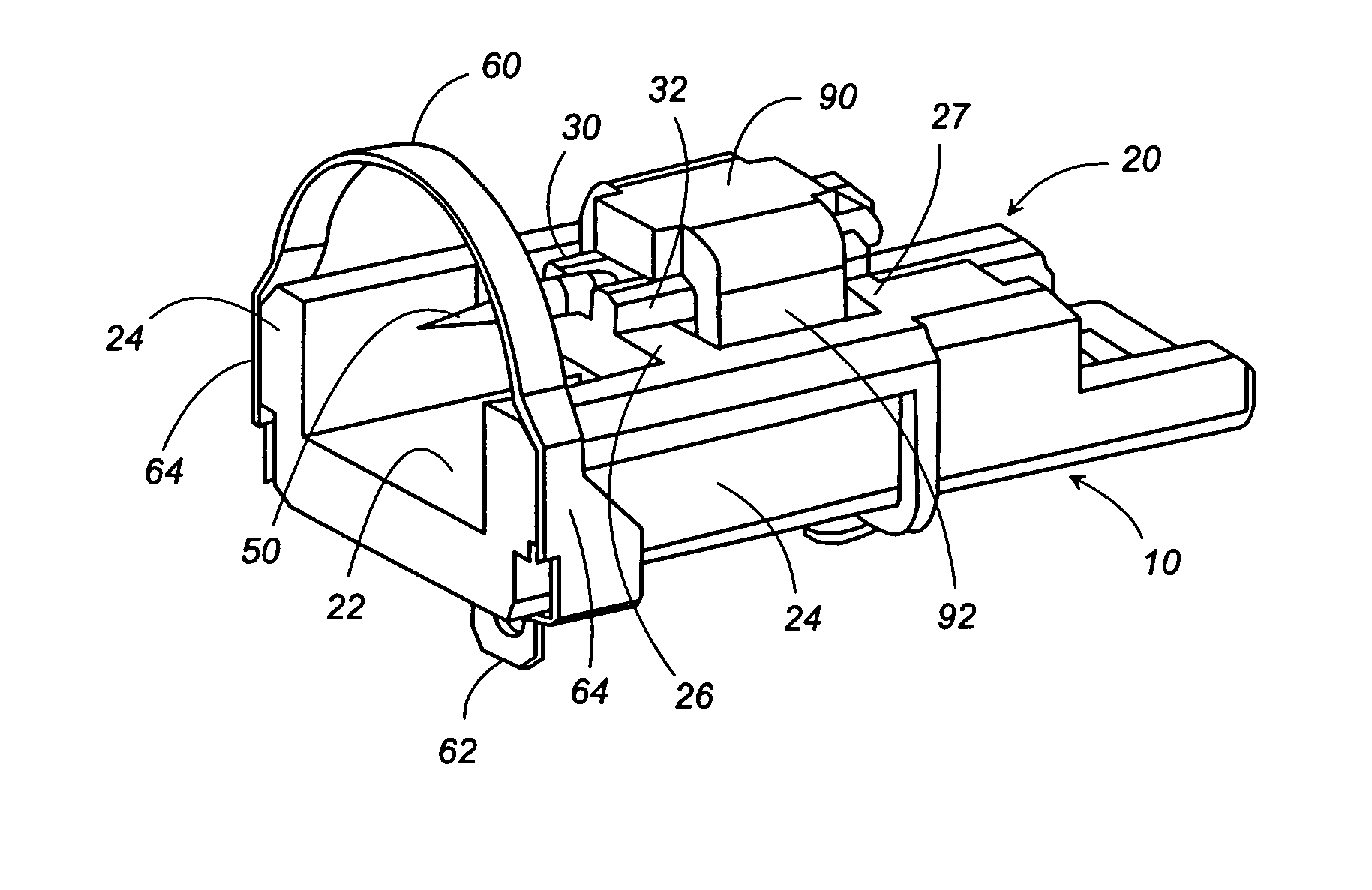
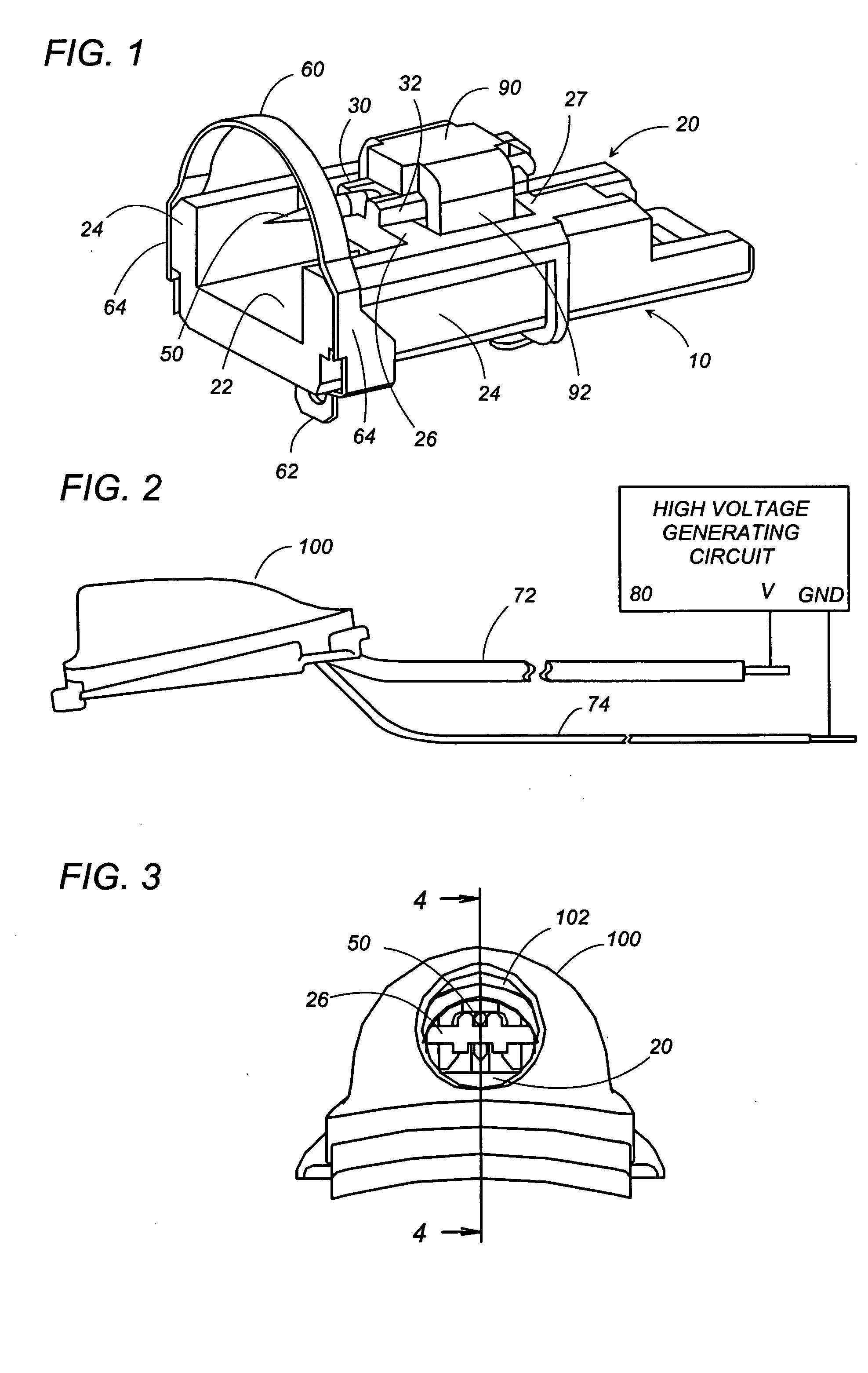
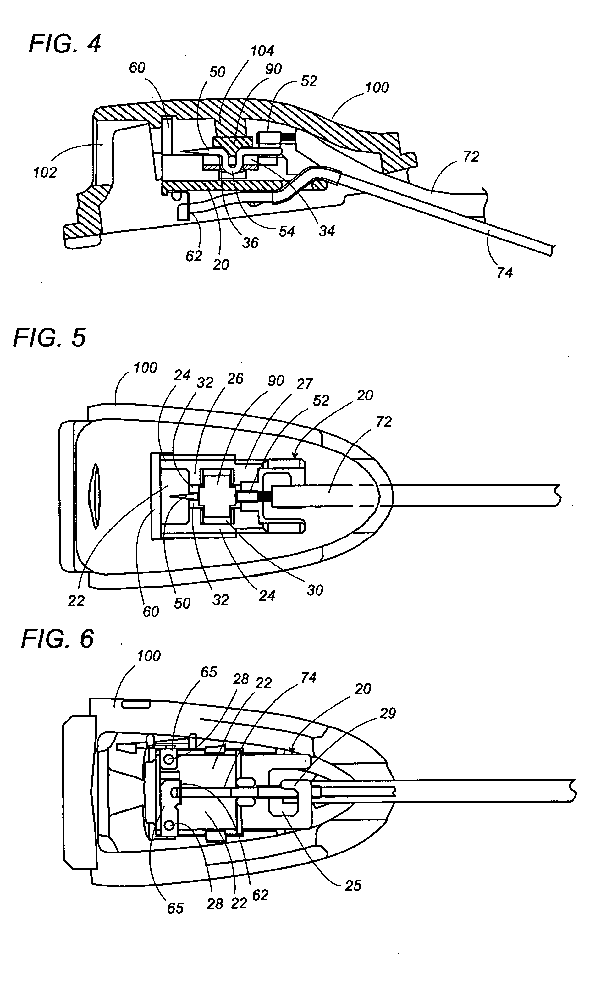
[0025] Referring now to FIGS. 1 to 6, there is shown an ion generating unit in accordance with a preferred embodiment of the present invention. The ion generating unit 10 includes a dielectric base 20 which is molded from an electrically insulating plastic material into a generally flat rectangular configuration for carrying a needle electrode 50 and a ground electrode 60. The base 20 includes a bottom plate 22, side ribs 24 upstanding from the lateral edges of the plate 22, and a socket 30 holding the needle electrode 50. The needle electrode 50 has a pointed tip at its front end and is provided at its rear end with a voltage terminal 52 for soldering connection with a wire 72 leading to a voltage output of a high voltage generating circuit 80. The needle electrode 50 is aligned with the length of the base 20 and is disposed at a width center of the base 20 with its pointed tip receded from the front edge of the base 20. The ground electrode 60 is disposed at the front end of the b...


PUM


Abstract

An ion generating unit is made compact, yet avoids the undesired arc discharge for successfully generating the ions. The ion generating unit includes a dielectric base having a length and carrying a needle electrode and a ground electrode. The needle electrode has a pointed tip and is adapted to receive a high electric voltage relative to the ground electrode for electrically charging particles present in the surrounding air. The dielectric base being a polyhedron having multiple faces including a first face and a second face which are different from each other and have the length of the dielectric base. The needle electrode is mounted on or in a closely adjacent relation to the first face, and has its pointed tip directing forwardly along the length of the dielectric base with the pointed tip receded from the front end of the base. The ground electrode is mounted at the front end of the base in longitudinally spaced relation with the pointed tip. The ground electrode include anchor ends only by which the ground electrode is secured to the base. The anchor ends are fixed to the second face of the base, but not to the first face. Thus, the creepage distance between the electrodes extends over the first face and also the second face of the dielectric base, thereby being given an elongated distance relative to the air path between the electrodes for successfully generating the ions.

Description

TECHNICAL FIELD [0001] The present invention is directed to an ion generating unit for generating ions in the surrounding air by developing the corona discharge around a needle electrode receiving a high voltage relative to an associated ground electrode. BACKGROUND ART [0002] European Patent Publication EP 1 208 766 A2 discloses a like ion generating unit that includes a needle electrode and a ground electrode for developing the corona discharge to generate the ions in the air around the pointed tip of the needle electrode by applying a high voltage across the electrodes. The unit has a dielectric tube which surrounds the needle electrode and the ground electrode in the form of arc or partially cut ring. The needle electrode is held in a center of the dielectric tube, while the ground electrode is disposed at one longitudinal end of the tube in a longitudinally spaced relation to the pointed tip of the needle electrode. However, the use of the tube necessitates a dead space at a po...

Claims


Application Information

Patent Timeline
IPC IPC(8): B03C3/02A61L9/22A61N1/44B03C3/40B03C3/41H01T19/04H01T23/00H05F3/04
CPCH01T23/00A61N1/44
Inventor NAKASONE, HIDETOSHISAIDA, ITARUITO, KENGO
Owner MATSUSHITA ELECTRIC WORKS LTD
Why Eureka
Try Eureka