Cask and method of manufacturing the cask

a cask and casing technology, applied in the field of casks, can solve the problems of troublesome welding operation, difficult assembly of the cask, and difficulty in manual welding, so as to improve the thermal conductivity, and provide the strength of the sheet members

Inactive Publication Date: 2005-06-02
MITSUBISHI HEAVY IND LTD
View PDF18 Cites 14 Cited by
  • Summary
  • Abstract
  • Description
  • Claims
  • Application Information

AI Technical Summary

Benefits of technology

[0013] As the heat conductive fins are welded along both sides of the belt-like member A with a margin left along edges of the both sides, it is possible to separate the welded joints between the belt-like member A and the belt-like member B from the welded joints between the heat conductive fin and the belt-like member A, by welding the belt-like members A and B together near the edges thereof. With this arrangement, it is possible to prevent local concentration of thermally influenced sections.
[0065] Furthermore, the cask comprises a body internally provided with a basket that accommodates radioactive materials such as spent fuel assemblies, and a plurality of sheet members provided around the body, with a part of each of the members being in contact with the body, another part of the member constituting an external surface of the cask, and still another part of the member being connected to an adjacent sheet member. The sheet member further includes a fitting section with the body, and the fitting section has higher weldability with respect to the body than other portions of the sheet member. Therefore, it is possible to improve the thermal conductivity, and it becomes possible to easily weld the sheet members to the body.

Problems solved by technology

However, since the cask 500 has a height of about 6 m and the space formed between the external cylinder 503 and the heat conductive fins 508 is extremely narrow and long, it is extremely difficult to manually carry out welding.
Consequently, there has been a problem that the welding operation is troublesome.
Particularly, when only a traditional welding machine exists in an assembling plant, it is difficult to assemble the cask.
This problem becomes serious in foreign countries where the assembling technique has not been developed.
However, according to the above conventional cask 1500, as the stripes 1502 have the fins 1504 welded, there has been a problem that the temperature is distributed over the external surface, and it is not possible to radiate heat uniformly.
This has not been desirable in terms of heat radiation efficiency.

Method used


Image

  • Cask and method of manufacturing the cask
  • Cask and method of manufacturing the cask
  • Cask and method of manufacturing the cask

Examples


first embodiment

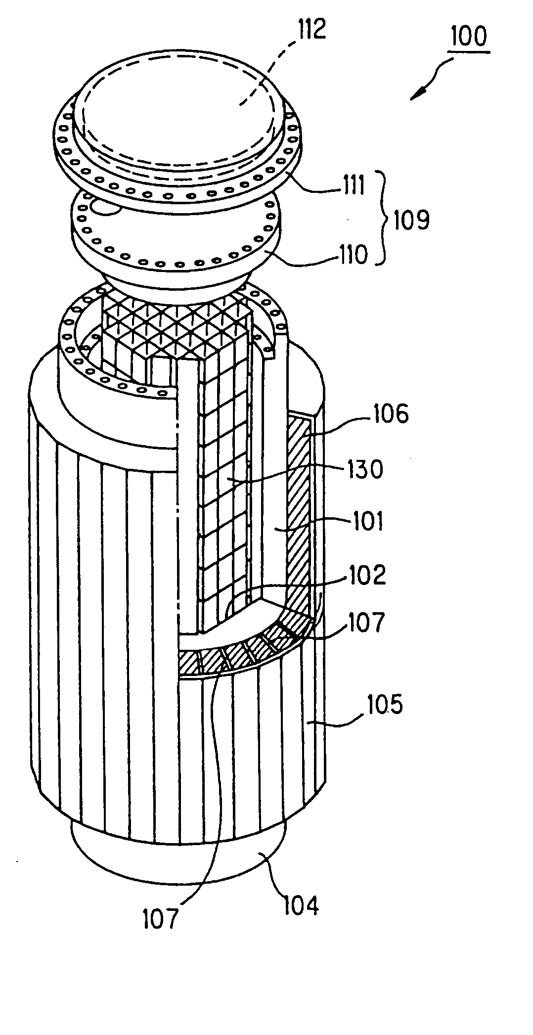
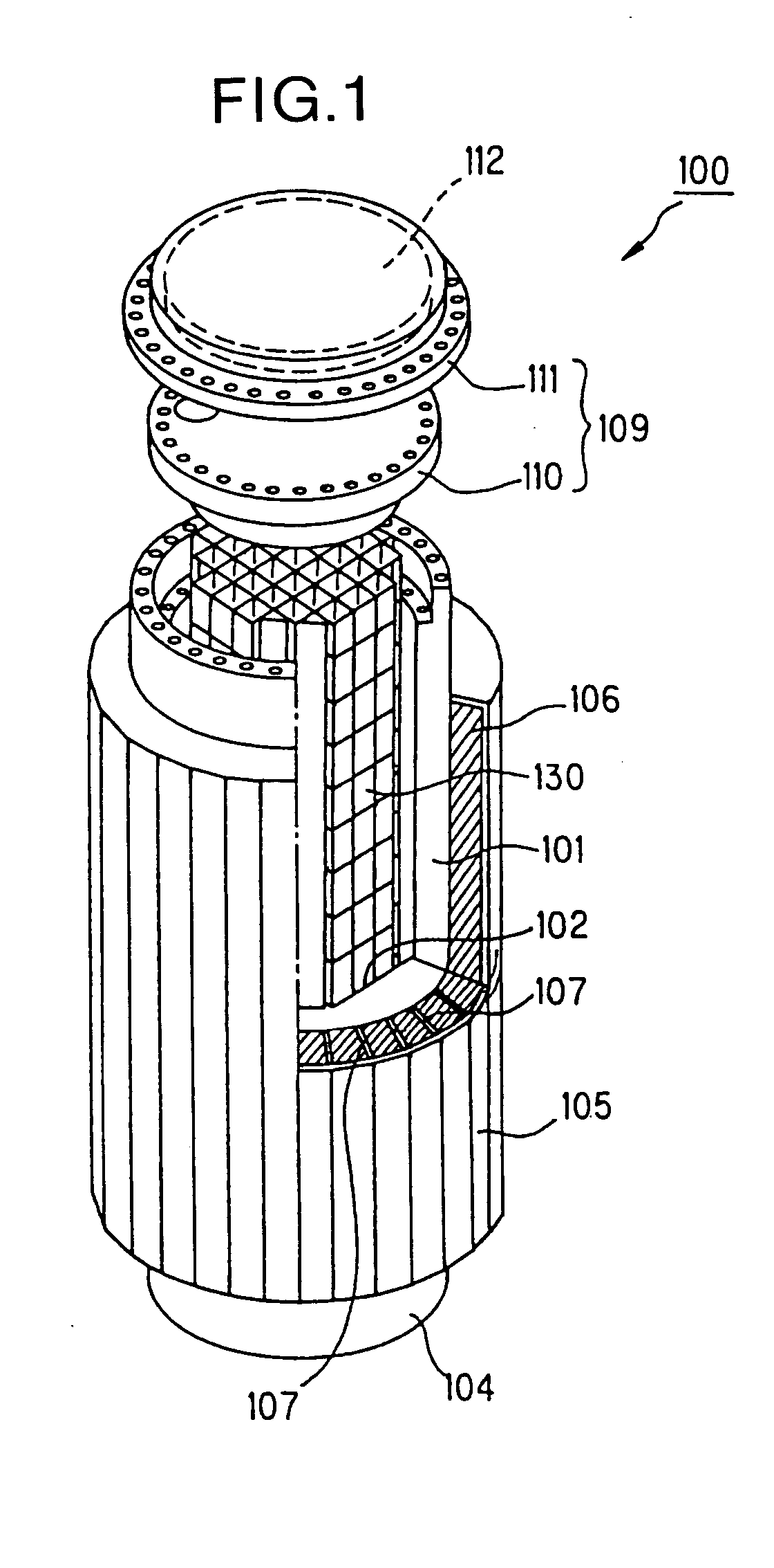
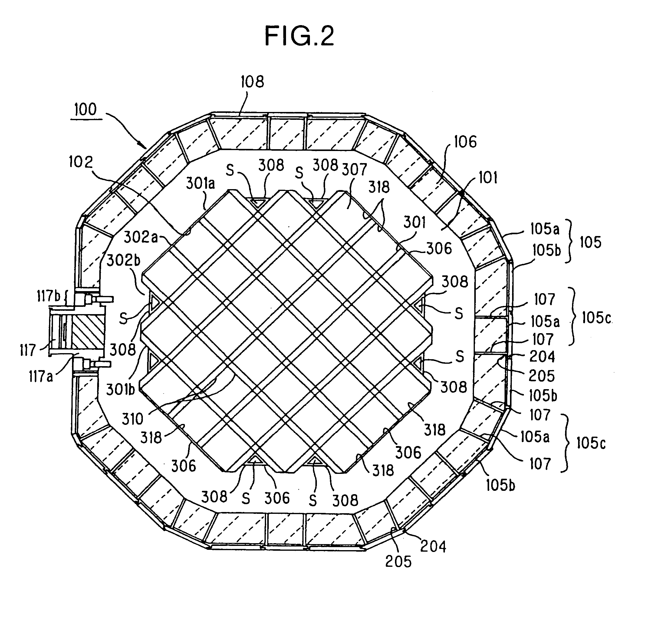
[0109]FIG. 1 is a perspective view which shows a cask according to the first embodiment of this invention. FIG. 2 is a cross-sectional view of the cask shown in FIG. 1 in its radial direction. A cask 100 according to this first embodiment is machined so as to have the internal surface of a cavity 102 of a body 101 matched with an external peripheral shape of a basket 130. The internal surface of the cavity 102 is machined by milling with an exclusive machining apparatus to be described later. The body 101 and a bottom plate 104 are forged using carbon steel having a gamma-ray shielding function. It is possible to use stainless steel instead of carbon steel. The body 101 and the bottom plate 104 are connected together by welding. In order to secure sealing performance of a pressure-resistant vessel, a metallic gasket is provided between a primary lid 110 and the body 101.

[0110] A resin 106 that is a polymer material containing much hydrogen and has a neutron shielding function is fi...

second embodiment

[0142]FIG. 15 is an explanatory view of a cask according to the second embodiment of this invention. This cask is characterized in that an external cylinder 216 has an angular shape in its cross section. Heat conductive fins 107 are welded to both edges of a belt-like member 216a that is formed in an angular shape by bending (welded joints 205), thereby to form a unit. These units are welded onto bulge portions 201 of the body 101 (welded joints 206). Further, belt-like member 216b is formed by bending in the similar manner. The stage section 203 of the belt-like member 216b is engaged with the stage section 202 of the belt-like member 216a and is welded from the outside (welded joints 204). Honeycomb members are provided on the internal surfaces of the belt-like members 216a and b. A resin that absorbs neutron is filled in spaces formed with the belt-like members 216a or 216b and the heat conductive fins 107.

[0143] In the above structure, it is possible to carry out the entire wel...

third embodiment

[0145]FIG. 17 is an explanatory view which shows a cask according to the third embodiment of this invention. An external cylinder 220 of this cask is characterized in that a unit 220a having a T shape in its cross section is prepared by welding (welded joints 222) the heat conductive fin 107 at the center of a belt-like member 105a. The welding procedure is approximately similar to that of the first embodiment. First, the heat conductive fin 107 is welded to the belt-like member 105a to provide the unit 220a. The welding of the heat conductive fin 107 and the belt-like member 105a may be carried out from one side, or may be carried out from both sides in order to secure strength (welded joints 222). Next, these units 220a are welded to the body 101 at predetermined intervals. The body 101 is provided with a bulge portion 201, and the heat conductive fin 107 is welded on the bulge portion 201. Further, the welding is carried out from both sides of the heat conductive fin 107 in order...


PUM


Abstract

Heat conductive fins (107) are welded along both sides of a belt-like member (105a) with a margin left along edges of the both sides, thereby to form a unit (105c). The unit (105c) is welded to a body (101) with the heat conductive fins (107) from the outside of each fin. Next, another belt-like member (105b) is covered over a gap between adjacent belt-like members (105a, 105a), and these members are welded from the outside. With this arrangement, there is no need to weld in a narrow and long space and the entire welding step is carried out from the outside, which makes it easier to assemble a cask.

Description

TECHNICAL FIELD [0001] The present invention relates to a cask that accommodates and stores spent fuel assemblies after finishing combustion and whose assembly is easily performed, and a method of manufacturing the cask. BACKGROUND ART [0002] A nuclear fuel assembly that is at its end period of a nuclear fuel cycle, finishes its combustion, and cannot be used any more, is called spent nuclear fuel. The spent nuclear fuel containing high radioactive materials such as FP requires thermal cooling, and is, therefore, cooled at a cooling pit of a nuclear power plant for a predetermined period of time (one to three years). Then, the spent nuclear fuel is accommodated in a cask as a shielding container, and the cask is conveyed to a reprocessing facility by track or the like, and is stored there. Each spent fuel assembly is inserted into each cell of a basket installed in the cask, thereby to secure proper holding force against vibration during the transportation. [0003] There are various ...

Claims


Application Information

Patent Timeline
Patent Type & Authority Applications(United States)
IPC IPC(8): G21C19/32G21C19/06G21F5/008G21F5/10
CPCG21F5/008G21F5/10G21Y2004/40G21Y2002/60G21Y2004/30G21Y2002/302Y02E30/30G21C19/32
Inventor OHSONO, KATSUNARIMATSUOKA, TOSHIHIROHODE, SUGURUOOKAME, SHINJI
Owner MITSUBISHI HEAVY IND LTD
Why Eureka
Try Eureka