Method and apparatus to synthesize and defeat video copy protection signals

a technology of video copy protection and video synthesizer, which is applied in the field of video copy protection signal synthesizer and defeating video copy protection signal, can solve the problems of low contrast to synchronizing problems, video programs that are not recordable suffer from artifacts, and produce a recording lacking entertainment value, etc., and achieves the effect of defeating copy protection signal

Active Publication Date: 2005-06-02
ALL MEDIA GUIDE +10
View PDF39 Cites 10 Cited by
  • Summary
  • Abstract
  • Description
  • Claims
  • Application Information

AI Technical Summary

Benefits of technology

[0014] The copy protection defeating mechanisms of this invention can also be used in combination with any of the defeat inventions mentioned above. For example, to defeat the copy protection process, one can shift (delay) the AGC pulse by about 1.5 μseconds away from the preceding pseudo sync pulse and then trim the trailing edge of the preceding pseudo sync pulse by 0.6 μsecond. Thus a gap of about 2.1 μseconds exists between the trailing edge of the trimmed pseudo sync pulse and the leading edge of the delayed AGC pulse. If this gap is, for example, near blanking level for 2.1 μseconds, then the VCR will sample the voltage in the gap instead of the added AGC pulses for its AGC amplifier. By sampling this gap voltage near blanking level, the copy protection signal is then nullified. Alternatively, the gap voltage level may be set above or below blanking level. It is important to note that by simply delaying or shifting the position of the leading edge of the AGC pulse relative to the trailing edge of the pseudo sync pulse, the gap between the pseudo sync pulses and the AGC pulses will nullify or partially nullify the effects of the AGC copy protection signal. It is also possible to create this gap in other ways such as moving the trailing edge of pseudo sync pulse away from the leading edge of the upcoming AGC pulse, or some combination of moving the position of both the AGC pulse and pseudo sync pulse to form a gap that would defeat the copy protection process. Typical gap durations of 1.5 μseconds or more have proved effective in defeating the copy protection signal. Compounding the narrowing of the pseudo sync pulses and / or AGC pulses with this gap further enhances defeating the copy protection signal.

Problems solved by technology

The Hollywood movie industry is very concerned about the unauthorized copying of movies and programs.
The copy protected video is viewable on a TV set but it produces a recording lacking any entertainment value.
That is, the video programs that are not recordable suffer from artifacts ranging from low contrast to synchronizing problems.

Method used


Image

  • Method and apparatus to synthesize and defeat video copy protection signals
  • Method and apparatus to synthesize and defeat video copy protection signals
  • Method and apparatus to synthesize and defeat video copy protection signals

Examples


Embodiment Construction

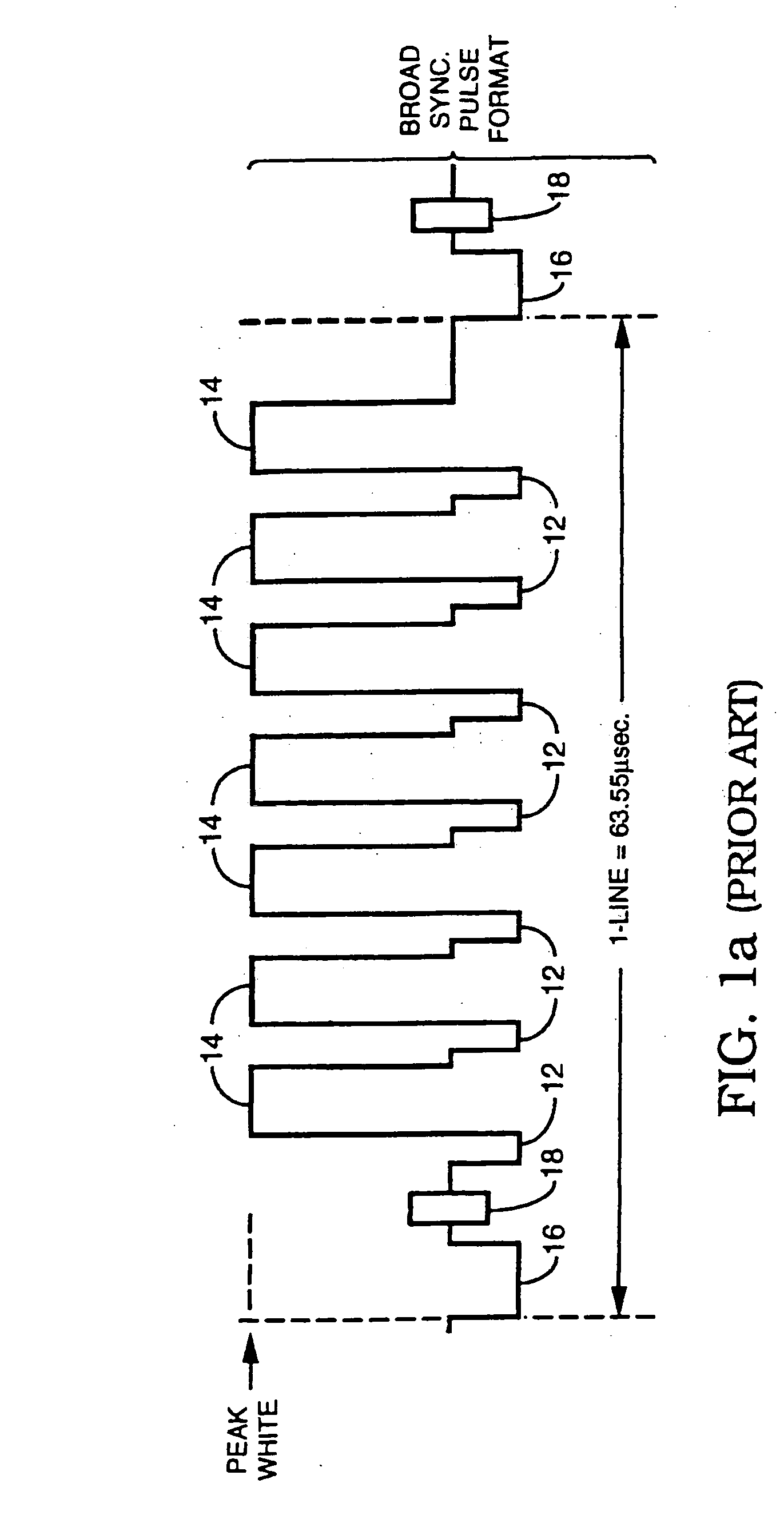
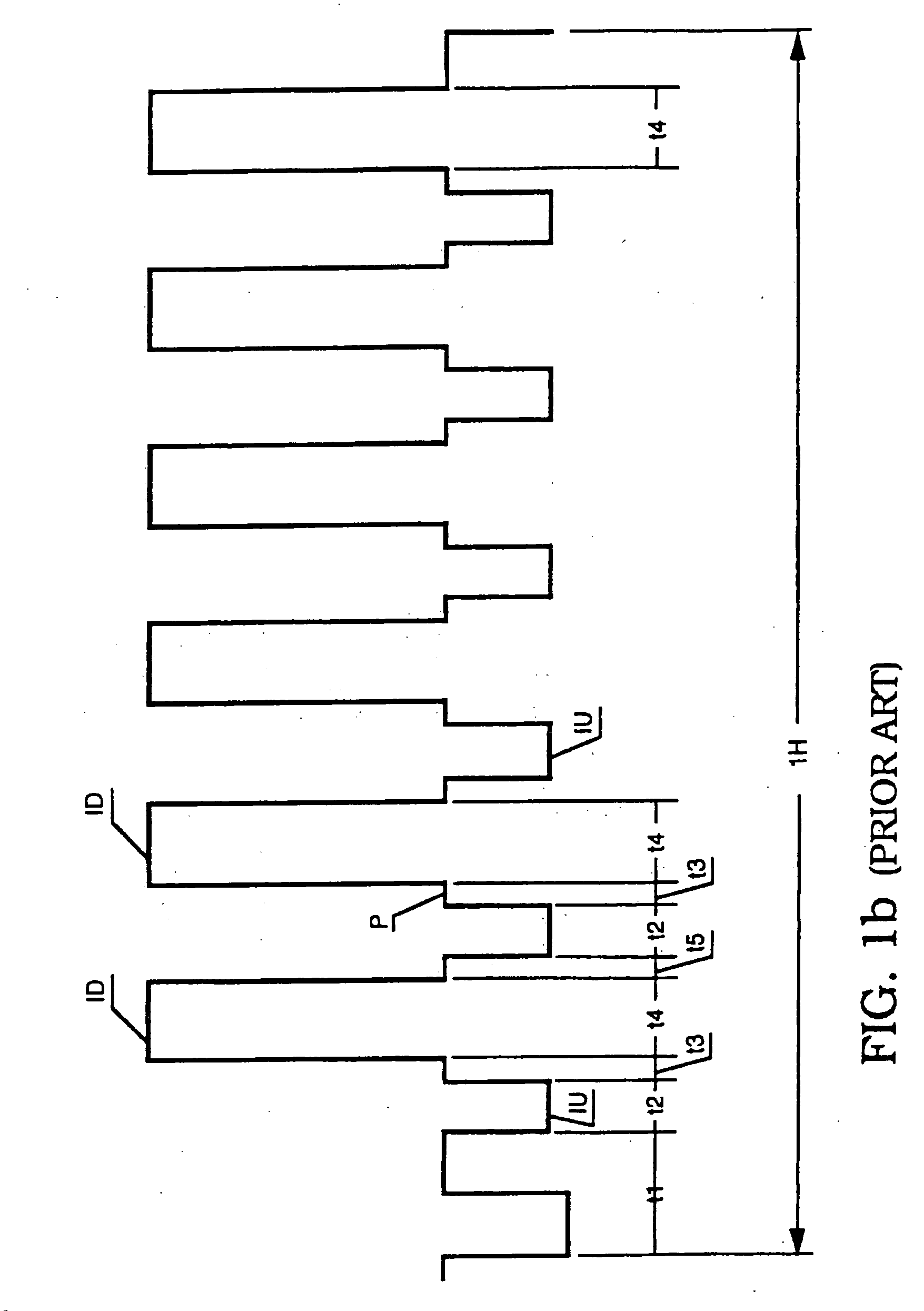
[0034] As previously discussed, FIGS. 1a and 1b illustrate prior art copy protection and copy protection defeating signals, respectively.

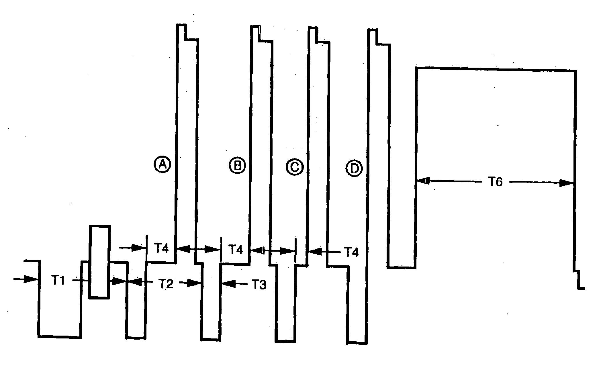
[0035]FIG. 2 illustrates various waveforms corresponding to ways that AGC pulses can be delayed to provide the copy protection defeating technique of the invention. First, the waveform D in FIG. 2 illustrates the AGC pulse and pseudo sync pulse at the normal position previously shown in FIG. 1a which causes copy protection. Waveforms A to C show various delays or gaps between the trailing edge of pseudo sync pulse and the leading edge of the respective AGC pulse. Waveforms A and B are effective in turning off the copy protection signal while waveform C causes partial reduction or turn off of the copy protection signal. For effective defeat of the copy protection signal it follows that waveforms A and B are preferable.

[0036] For a new copy protection signal that is dynamically varied from on to off, one technique of the invention starts for exampl...


PUM


Abstract

A method and apparatus for defeating copy protection signals in a video signal, and also for providing copy protection signals for a video signal, is disclosed. The defeat technique generally utilizes a particular pulse position shifting, modulation, etc., of AGC, normal sync and / or pseudo sync pulses to increase the separation between the pulses. Various embodiments are disclosed including selective shifting of the relative positions of either the sync / pseudo sync or AGC pulses, trimming portions of the sync / pseudo sync and / or the AGC pulses and narrowing of either the sync / pseudo sync and / or the AGC pulses, all to provide the selective position separation between the sync / pseudo sync and AGC pulses. The copy protection technique includes various embodiments for dynamically varying the sync / pseudo sync and AGC pulse separation by applying a modulation of the above position shifting, trimming and / or narrowing techniques over selected time periods to cycle from the copy protection condition to the copy protection defeat condition, back to the copy protection condition.

Description

CROSS REFERENCE TO RELATED APPLICATIONS [0001] This invention is related to commonly owned U.S. Pat. No. 4,631,603 entitled “METHOD AND APPARATUS FOR PROCESSING A VIDEO SIGNAL SO AS TO BE ABLE TO PROHIBIT THE MAKING OF ACCEPTABLE VIDEO TAPE RECORDINGS THEREOF” which issued on Dec. 12, 1986; to U.S. Pat. No. 4,695,901 entitled “METHOD AND APPARATUS FOR REMOVING PSEUDO-SYNC PULSES AND / OR AGC PULSES FROM A VIDEO SIGNAL” which issued on Sep. 22, 1987; to U.S. Pat. No. 4,907,093 for METHOD AND APPARATUS FOR PREVENTING THE COPYING OF A VIDEO PROGRAM” which issued Mar. 6, 1990; to U.S. Pat. No. 4,819,098 for “METHOD AND APPARATUS FOR CLUSTERING MODIFICATIONS MADE TO A VIDEO SIGNAL TO INHIBIT THE MAKING OF ACCEPTABLE VIDEO TAPE RECORDINGS” which issued on Apr. 4, 1989; to U.S. Pat. No. 5,157,510 for “METHOD AND APPARATUS FOR DISABLING ANTI-COPY PROTECTION SYSTEM IN VIDEO SIGNALS USING PULSE NARROWING which issued on Oct. 20, 1992; to U.S. Pat. No. 5,194,965 for “METHOD AND APPARATUS FOR DIS...

Claims


Application Information

Patent Timeline
Patent Type & Authority Applications(United States)
IPC IPC(8): H04N5/913
CPCH04N2005/91314H04N5/913
Inventor QUAN, RONALD
Owner ALL MEDIA GUIDE
Why Eureka
Try Eureka